2017 YAMAHA KODIAK 700 4WD
[x] Cancel search: 4WDPage 9 of 178

EBU17421
TABLE OF CONTENTS
LOCATION OF THE WARNING AND
SPECIFICATION LABELS .............................. 1-1
SAFETY INFORMATION ................................ 2-1
DESCRIPTION................................................ 3-1Left view ...................................................... 3-1
Right view.................................................... 3-1
Controls and instruments............................ 3-2
INSTRUMENT AND CONTROL
FUNCTIONS ................................................... 4-1 Main switch ................................................. 4-1
Indicator lights and warning lights .............. 4-2
Multi-function display (YFM70KPXH / YFM70KPHH / YFM70KPSH /
YFM70KPAH) ............................................ 4-6
Handlebar switches .................................... 4-9
Drive lever “2WD”/“4WD” (YFM70KDXH / YFM70KPXH / YFM70KPHH /
YFM70KPAH) .......................................... 4-15
Throttle lever ............................................. 4-16
Speed limiter ............................................. 4-17
Front brake lever ....................................... 4-18 Brake pedal and rear brake lever ............. 4-18
Drive select lever ...................................... 4-19
Fuel tank cap ............................................ 4-19
Fuel ........................................................... 4-19
Seat .......................................................... 4-21
Storage compartment............................... 4-22
Front carrier .............................................. 4-23
Rear carrier ............................................... 4-23
Adjusting the front and rear shock
absorber assemblies (YFM70KPXH /
YFM70KPHH / YFM70KPSH /
YFM70KPAH).......................................... 4-24
Trailer hitch (YFM70KPXH / YFM70KPHH / YFM70KPSH /
YFM70KPAH).......................................... 4-25
Auxiliary DC jack....................................... 4-26
PRE-OPERATION CHECKS .......................... 5-1 Fuel ............................................................. 5-3
Engine oil .................................................... 5-3
Final gear oil ............................................... 5-3
Differential gear oil ...................................... 5-3
Coolant ....................................................... 5-3
Front and rear brakes ................................. 5-3UB1661E0.book Page 1 Thursday, May 12, 2016 2:47 PM
Page 18 of 178

1-7
1
**.* kPa
*.** kgf/cm²*.* psi **.* kPa
*.** kgf/cm²
*.* psi
This pictogram shows trailer Hitch Tow
weight limit. (Combined weight of the trailer
and all cargo in the trailer.)
Overloading can cause loss of control.
Loss of control can result in severe injury or
death.
This unit contains high-pressure nitrogen
gas.
Mishandling can cause an explosion. Do not
incinerate, puncture or open.
Use unleaded gasoline only.
Measure the tire pressure when the tires are
cold.
Turning the ATV in 4WD-LOCK
(“DIFF.LOCK”) takes more effort.
Operate at a slow speed and allow extra
time and distance for maneuvers to avoid
loss of control.
Adjust the tire pressure.
Improper tire pressure can cause loss of
control.
Loss of control can result in severe injury or
death. This pictogram shows the loading limits
and/or maximum load capacity for this ATV.
Follow all load limits and other loading
guidelines in this manual.
Load may include the driver, passenger,
human protective gear, accessories, goods,
luggage, and all other load related items.
Make sure you do not exceed the load limits.
Overloading can cause loss of control.
Loss of control can result in severe injury or
death.
This pictogram shows trailer Hitch Tongue
weight limit. (Weight on the trailer tongue.)
Overloading can cause loss of control.
Loss of control can result in severe injury or
death.
UB1661E0.book Page 7 Thursday, May 12, 2016 2:47 PM
Page 31 of 178

3-2
3
EBU17714Controls and instrumentsYFM70KDXHYFM70KPXH / YFM70KPHH / YFM70KPSH /
YFM70KPAH1. Drive select lever
2. Rear brake lever
3. Handlebar switches
4. Horn switch
5. Drive lever “2WD”/“4WD”
6. Warning and indicator lights
7. Front brake fluid reservoir
8. Front brake lever
9. Throttle lever
10.Auxiliary DC jack
11.Main switch123
4 5 6 7 8 9 10 11
1. Drive select lever
2. Rear brake lever
3. Handlebar switches
4. Horn switch
5. Drive lever “2WD”/“4WD” (YFM70KPXH / YFM70KPHH /
YFM70KPAH)
6. Multi-function display
7. Front brake fluid reservoir
8. On-Command four-wheel-drive/differential gear lock switch (YFM70KPSH)
9. Front brake lever
10.Throttle lever
11.Auxiliary DC jack
12.Main switch123 67
8 9 10 11 12
45
UB1661E0.book Page 2 Thursday, May 12, 2016 2:47 PM
Page 37 of 178

4-5
4
EBU30571Electric Power Steering warning light “EPS”
(for EPS model)
This warning light comes on when the key is
turned to “ ” (on), and then goes off once the
engine is started. If the warning light remains on or
comes on after the engine is started, the EPS sys-
tem may not be working correctly. When this oc-
curs, have a Yamaha dealer check the EPS
system.
The electrical circuit of the warning light can be
checked by turning the key to “ ” (on). If the
warning light does not come on, have a Yamaha
dealer check the electrical circuit.TIPIf the engine is stopped using the engine stop
switch and the key is in the “ ” (on) position,
the EPS warning light comes on to indicate that
the power assistance for the steering is not
functioning.
If the steering load is too heavy (i.e., excessive
steering use when the ATV is traveling at a slow
speed), the power assist is reduced to protect
the EPS motor from overheating.
EBU34250Four-wheel-drive indicator light “ ”
(YFM70KDXH)
This indicator light comes on when the drive lever
is set to the “4WD” position.TIPDue to the synchronizing mechanism in the differ-
ential gear case, the light may not come on until
the ATV starts moving. Four-wheel-drive indicator “ ” (YFM70KPXH /
YFM70KPHH / YFM70KPSH / YFM70KPAH)
This indicator comes on when the drive lever or
the On-Command four-wheel-drive switch is set
to the “4WD” position.TIPDue to the synchronizing mechanism in the differ-
ential gear case, the indicator may not come on
until the ATV starts moving.
UB1661E0.book Page 5 Thursday, May 12, 2016 2:47 PM
Page 38 of 178

4-6
4On-Command differential gear lock
indicator “ ” and indicator light “DIFF. LOCK”
(YFM70KPSH)
This indicator and indicator light come on when
the On-Command differential gear lock switch is
set to the “LOCK” position.
TIPWhen the On-Command differential gear lock
switch is set to “LOCK” or “4WD”, the
indicator “ ” and the indicator light “DIFF. LOCK”
will flash until the differential gear is completely
locked or unlocked. If the indicator and the indica-
tor light continue to flash, the differential is not
completely locked or unlocked. In this case, start
moving to allow time for the differential to lock or
unlock.
EBU30498Multi-function display (YFM70KPXH /
YFM70KPHH / YFM70KPSH /
YFM70KPAH)The multi-function display is equipped with the
following:
speedometer
odometer1. “SELECT” button
2. “RESET” button
3. “CLOCK” button
4. Speedometer
5. Fuel gauge
6. Clock/Hour meter
7. Odometer/Tripmeter A/Tripmeter B
4
5
7
6
123
UB1661E0.book Page 6 Thursday, May 12, 2016 2:47 PM
Page 44 of 178

4-12
4es with the riding speed. You may lose control
and have an accident if you cannot make a
sharp enough turn for the speed you are trav-
eling.
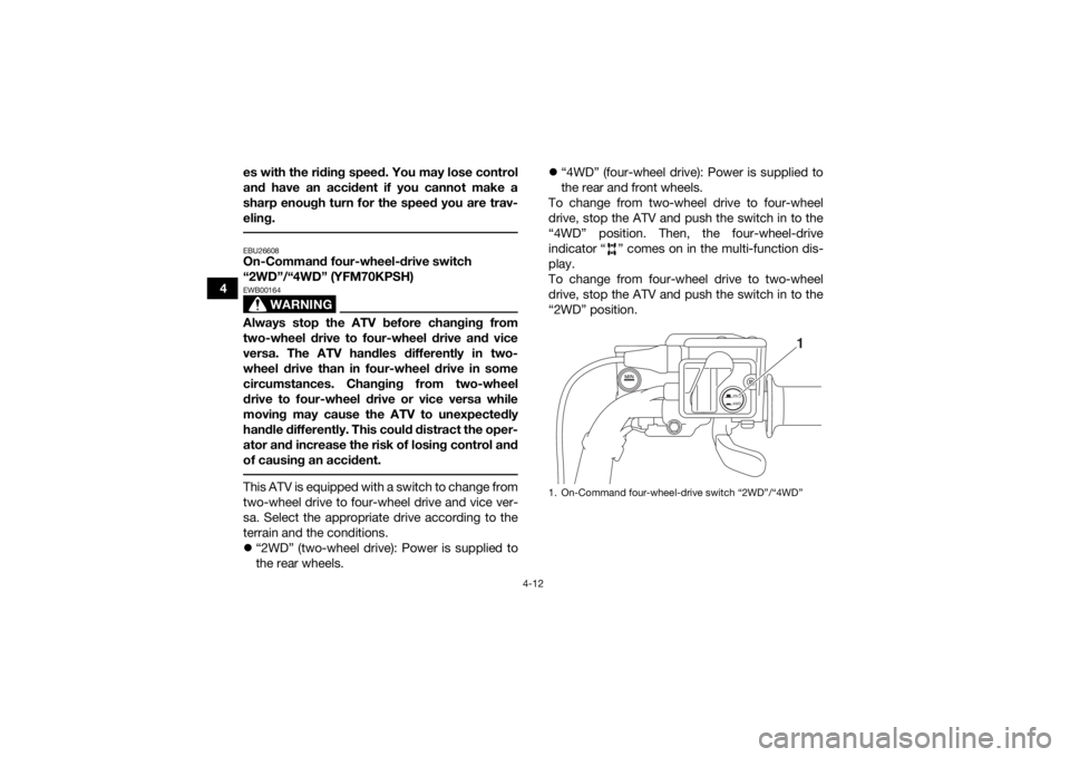
EBU26608On-Command four-wheel-drive switch
“2WD”/“4WD” (YFM70KPSH)
WARNING
EWB00164Always stop the ATV before changing from
two-wheel drive to four-wheel drive and vice
versa. The ATV handles differently in two-
wheel drive than in four-wheel drive in some
circumstances. Changing from two-wheel
drive to four-wheel drive or vice versa while
moving may cause the ATV to unexpectedly
handle differently. This could distract the oper-
ator and increase the risk of losing control and
of causing an accident. This ATV is equipped with a switch to change from
two-wheel drive to four-wheel drive and vice ver-
sa. Select the appropriate drive according to the
terrain and the conditions.
“2WD” (two-wheel drive): Power is supplied to
the rear wheels.
“4WD” (four-wheel drive): Power is supplied to
the rear and front wheels.
To change from two-wheel drive to four-wheel
drive, stop the ATV and push the switch in to the
“4WD” position. Then, the four-wheel-drive
indicator “ ” comes on in the multi-function dis-
play.
To change from four-wheel drive to two-wheel
drive, stop the ATV and push the switch in to the
“2WD” position.
1. On-Command four-wheel-drive switch “2WD”/“4WD”
2WD
4WD
1
UB1661E0.book Page 12 Thursday, May 12, 2016 2:47 PM
Page 45 of 178

4-13
4
EBU30463On-Command differential gear lock switch
“4WD”/“LOCK” (YFM70KPSH)
WARNING
EWB00132Always stop the ATV before changing from
four-wheel drive to four-wheel-drive differen-
tial gear lock or vice versa.
The ATV handles differently in four-wheel drive
than in differential gear lock in some circum-
stances. Changing from four-wheel drive to
differential gear lock or vice versa while mov-
ing may cause the ATV to handle differently un-
expectedly. This could distract the operator
and increase the risk of losing control and
causing an accident.
WARNING
EWB00141Always ride at a slow speed when the ATV is in
differential gear lock, and allow extra time and
distance for maneuvers.
All wheels turn at the same speed when the dif-
ferential gear is locked, so it takes more effort
to turn the ATV. The effort needed to turn in-
creases with the riding speed. You may losecontrol and have an accident if you cannot
make a sharp enough turn for the speed you
are traveling.
This ATV is equipped with a switch allowing you to
lock the differential gear when in four-wheel drive.
Select the appropriate switch position according
to the terrain and the conditions.
“4WD” (four-wheel drive): Power is supplied to
the rear and front wheels.
“LOCK” (four-wheel drive with the differential
gear locked): Power is supplied to the rear and
front wheels and the differential gear is locked.
Unlike in four-wheel drive, all wheels turn at the
same speed.
UB1661E0.book Page 13 Thursday, May 12, 2016 2:47 PM
Page 46 of 178

4-14
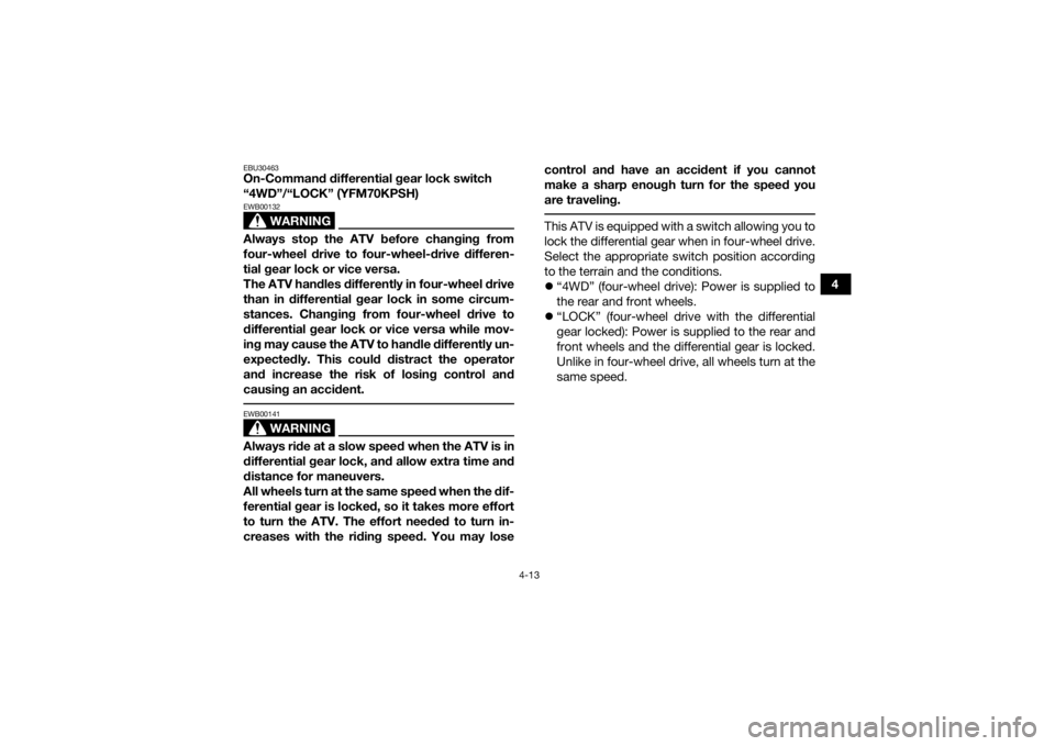
4To lock the differential gear in four-wheel drive,
make sure the On-Command four-wheel-drive
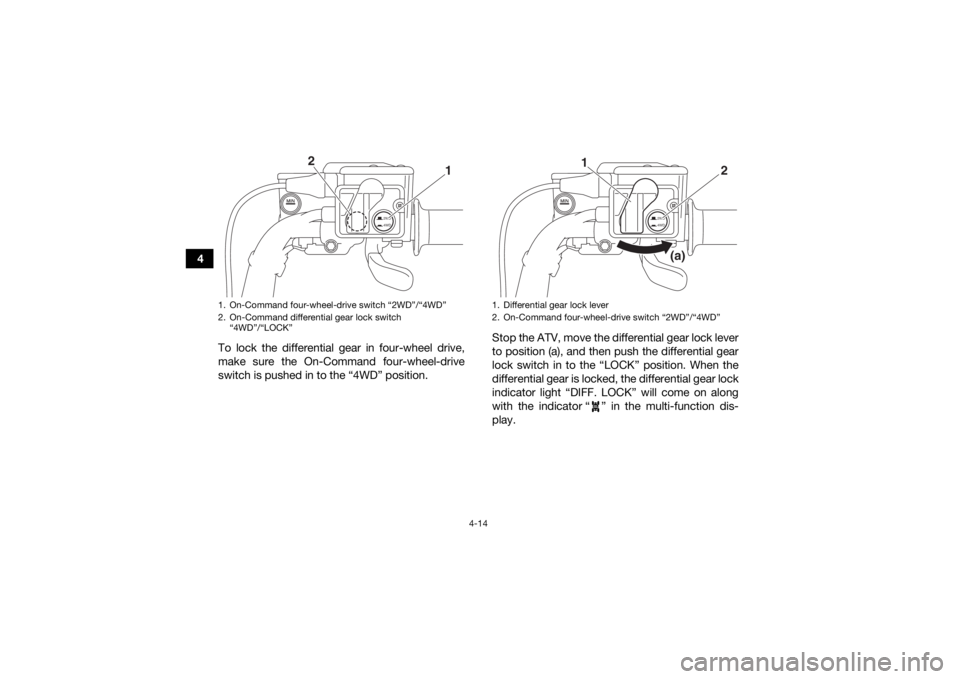
switch is pushed in to the “4WD” position. Stop the ATV, move the differential gear lock lever
to position (a), and then push the differential gear
lock switch in to the “LOCK” position. When the
differential gear is locked, the differential gear lock
indicator light “DIFF. LOCK” will come on along
with the indicator “ ” in the multi-function dis-
play.
1. On-Command four-wheel-drive switch “2WD”/“4WD”
2. On-Command differential gear lock switch
“4WD”/“LOCK”
2WD
4WD
1
2
1. Differential gear lock lever
2. On-Command four-wheel-drive switch “2WD”/“4WD”
2WD
4WD
2
1
(a)
UB1661E0.book Page 14 Thursday, May 12, 2016 2:47 PM