2017 YAMAHA GRIZZLY 350 warning light
[x] Cancel search: warning lightPage 8 of 140

EBU17421
TABLE OF CONTENTS
LOCATION OF THE WARNING AND
SPECIFICATION LABELS .............................. 1-1
SAFETY INFORMATION ................................ 2-1
DESCRIPTION................................................ 3-1Left view ...................................................... 3-1
Right view.................................................... 3-1
Controls and instruments............................ 3-2
INSTRUMENT AND CONTROL
FUNCTIONS ................................................... 4-1 Main switch ................................................. 4-1
Indicator lights and warning light ................ 4-2
Speedometer .............................................. 4-3
Handlebar switches .................................... 4-3
Throttle lever ............................................... 4-4
Speed limiter ............................................... 4-5
Front brake lever ......................................... 4-5
Brake pedal and rear brake lever ................ 4-6
Parking brake .............................................. 4-7
Drive select lever ......................................... 4-7
Fuel tank cap............................................... 4-8
Fuel ............................................................. 4-8 Fuel cock .................................................. 4-10
Starter (choke) ......................................... 4-11
Seat .......................................................... 4-12
Storage compartment............................... 4-13
Front carrier .............................................. 4-14
Rear carrier ............................................... 4-14
Adjusting the front shock absorber
assemblies .............................................. 4-14
Adjusting the rear shock absorber assembly ................................................ 4-15
PRE-OPERATION CHECKS .......................... 5-1 Fuel ............................................................. 5-3
Engine oil .................................................... 5-3
Final gear oil ............................................... 5-3
Front and rear brakes ................................. 5-3
Throttle lever ............................................... 5-4
Tires ............................................................ 5-4
Chassis fasteners ....................................... 5-6
Instruments, lights and switches ................ 5-6
OPERATION .................................................. 6-1 Starting a cold engine................................. 6-1
Starting a warm engine............................... 6-3UB1463E0.book Page 1 Thursday, August 4, 2016 2:12 PM
Page 29 of 140

4-2
4
EBU17817Indicator lights and warning lightEBU17871Neutral indicator light “NEUTRAL”
This indicator light comes on when the transmis-
sion is in the neutral position.EBU17851Reverse indicator light “REVERSE”
This indicator light comes on when the transmis-
sion is in the reverse position.
EBU26933Oil temperature warning light “ ”
This warning light comes on when the engine
overheats. When this occurs, stop the engine as
soon as it is safe to do so, and allow it to cool.
The electrical circuit of the warning light can be
checked by turning the key to “ON”, with the en-
gine stop switch set to “ ”, and then pushing the
start switch.
If the warning light does not come on while the
start switch is being pushed, or if the warning light
remains on after the start switch is released, have
a Yamaha dealer check the electrical circuit.
If the warning light stays on when the engine is
cool, have a Yamaha dealer check the electrical
circuit.NOTICEECB00011The engine may overheat if the ATV is over-
loaded. In this case, reduce the load to spec-
ification.
Start the engine after making sure that the
warning light is out. Continuous use while
the warning light is on may cause damage to
the engine.
1. Reverse indicator light “REVERSE”
2. Neutral indicator light “NEUTRAL”
3. Oil temperature warning light “ ”UB1463E0.book Page 2 Thursday, August 4, 2016 2:12 PM
Page 36 of 140

4-9
4of sparks, open flames, or other sources of
ignition such as the pilot lights of water heat-
ers and clothes dryers.
2. Do not overfill the fuel tank. When refueling, be sure to insert the pump nozzle into the fuel
tank filler hole. Stop filling when the fuel
reaches the bottom of the filler tube. Because
fuel expands when it heats up, heat from the
engine or the sun can cause fuel to spill out of
the fuel tank.
3. Wipe up any spilled fuel immediately.NOTICE: Immediately wipe off spilled fuel
with a clean, dry, soft cloth, since fuel may
deteriorate painted surfaces or plastic
parts.
[ECB00982]
4. Turn the fuel tank cap fully clockwise to make sure it is securely closed.
WARNING
EWB02532Gasoline is poisonous and can cause injury or
death. Handle gasoline with care. Never siphon
gasoline by mouth. If you should swallow some
gasoline or inhale a lot of gasoline vapor, or get
some gasoline in your eyes, see your doctor
1. Maximum fuel level
2. Fuel tank filler tube
Recommended fuel:Regular unleaded gasoline only
For Europe: Regular unleaded gasoline only
with a research octane number of 95 or
higher
Fuel tank capacity: 13.5 L (3.56 US gal, 2.97 Imp.gal)
Fuel reserve amount: 3.3 L (0.87 US gal, 0.73 Imp.gal)
UB1463E0.book Page 9 Thursday, August 4, 2016 2:12 PM
Page 50 of 140

6-1
6
EBU19882
OPERATION
EBU19902Read the Owner’s Manual carefully before riding
the ATV. If there is a control or function you do not
understand, ask your Yamaha dealer.
WARNING
EWB00632Read the Owner’s Manual carefully to become
familiar with all controls in order to help pre-
vent any loss of control, which could cause an
accident or injury. EBU26954Starting a cold engineNOTICEECB00151See the “Engine break-in” section on page 6-4
prior to operating the engine for the first time. 1. Set the parking brake.
2. Turn the fuel cock to “ON”.
3. Turn the key to “ON” and the engine stopswitch to “ ”. 4. Shift the drive select lever into the neutral po-
sition. The neutral indicator light should come
on. If the indicator light does not come on,
have a Yamaha dealer check the electrical
circuit.
TIPThe engine can be started under the following
conditions:
The drive select lever is in the neutral position.
The rear brake lever is applied with the drive se-
lect lever in any position. However, it is recom-
mended to shift into the neutral position before
starting the engine. 5. Use the starter (choke) in reference to the fi-
gure:
Position (1):
Cold engine start with ambient temperature
below 5 °C (40 °F).
Position (2):
Cold engine start with ambient temperature
between 0 °C (30 °F) and 30 °C (90 °F).
UB1463E0.book Page 1 Thursday, August 4, 2016 2:12 PM
Page 52 of 140

6-3
6
EBU20292Starting a warm engineFollow the same procedure as for starting a cold
engine, with the exception that the starter (choke)
is not required when the engine is warm. Instead,
start the engine with the throttle slightly open.EBU20384Operating the drive select lever and
driving in reverseNOTICEECB00171Before shifting, stop the ATV, otherwise the
transmission may be damaged. Shifting: Forward1. Bring the ATV to a complete stop.
2. Apply the brake pedal.
3. Shift from neutral to forward and vice versa by moving the drive select lever along the
shift guide.TIPMake sure that the drive select lever is completely
shifted into position.
4. Release the brake pedal, and then open thethrottle lever gradually.
Shifting: Reverse
WARNING
EWB00721Improper operation in reverse could make you
hit an obstacle or even a person behind you,
resulting in serious injury. When you shift into1. Drive select lever
2. F (Forward)
3. N (Neutral)
4. R (Reverse)
1
F2
N3R4
UB1463E0.book Page 3 Thursday, August 4, 2016 2:12 PM
Page 69 of 140

7-12
7
Select a large, flat, unpaved area to become famil-
iar with your ATV. Make sure that this area is free
of obstacles and other riders. You should practice
control of the throttle, brakes, and turning techni-
ques in this area before trying more difficult ter-
rain.
Set the parking brake and follow the instruction on
page 6-1 to start the engine. Once it has warmed
up you are ready to begin riding your ATV. With
the engine idling, return the starter (choke) to the
closed position and shift the drive select lever into
the forward position, then release the parking
brake. Apply the throttle slowly and smoothly.
The centrifugal clutch will engage and you will
start to accelerate. If the throttle is applied too
abruptly, the front wheels may lift off the ground,
resulting in a loss of directional control. Avoid
higher speeds until you are thoroughly familiar
with the operation of your ATV.
When slowing down or stopping, release the
throttle and apply the brakes smoothly and evenly.
Improper use of the brakes can cause the tires to
lose traction, reducing control and increasing the
possibility of an accident. TURNING YOUR ATV
WARNING
EWB01772Always follow proper procedures for turning as
described in this Owner’s Manual. Practice
turning at low speeds before attempting to turn
at faster speeds. Do not turn at speeds too fast
for your skills or the conditions. ATV could go
out of control, causing a collision or overturn. To achieve maximum traction on unpaved surfac-
es, the two rear wheels turn together at the same
speed. Therefore, unless the wheel on the inside
of the turn is allowed to slip or lose some traction,
the ATV will resist turning. A special turning tech-
nique must be used to allow the ATV to make
turns quickly and easily. It is essential that this skill
be learned first at low speed.
As you approach a curve, slow down and begin to
turn the handlebars in the desired direction. As
you do so, put your weight on the footboard to the
outside of the turn (opposite your desired direc-
tion) and lean your upper body into the turn. Use
the throttle to maintain an even speed through the
turn. This maneuver will let the wheel on the inside
of the turn slip slightly, allowing the ATV to make
the turn properly.
UB1463E0.book Page 12 Thursday, August 4, 2016 2:12 PM
Page 74 of 140

7-17
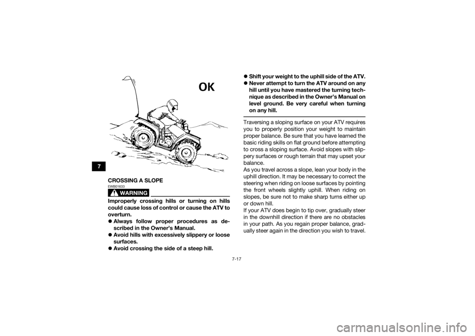
7CROSSING A SLOPE
WARNING
EWB01633Improperly crossing hills or turning on hills
could cause loss of control or cause the ATV to
overturn.
Always follow proper procedures as de-
scribed in the Owner’s Manual.
Avoid hills with excessively slippery or loose
surfaces.
Avoid crossing the side of a steep hill.
Shift your weight to the uphill side of the ATV.
Never attempt to turn the ATV around on any
hill until you have mastered the turning tech-
nique as described in the Owner’s Manual on
level ground. Be very careful when turning
on any hill.
Traversing a sloping surface on your ATV requires
you to properly position your weight to maintain
proper balance. Be sure that you have learned the
basic riding skills on flat ground before attempting
to cross a sloping surface. Avoid slopes with slip-
pery surfaces or rough terrain that may upset your
balance.
As you travel across a slope, lean your body in the
uphill direction. It may be necessary to correct the
steering when riding on loose surfaces by pointing
the front wheels slightly uphill. When riding on
slopes, be sure not to make sharp turns either up
or down hill.
If your ATV does begin to tip over, gradually steer
in the downhill direction if there are no obstacles
in your path. As you regain proper balance, grad-
ually steer again in the direction you wish to travel.
UB1463E0.book Page 17 Thursday, August 4, 2016 2:12 PM
Page 120 of 140

8-41
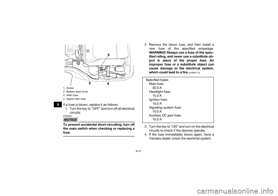
8If a fuse is blown, replace it as follows.
1. Turn the key to “OFF” and turn off all electrical circuits.
NOTICEECB00641To prevent accidental short-circuiting, turn off
the main switch when checking or replacing a
fuse.
2. Remove the blown fuse, and then install anew fuse of the specified amperage.
WARNING! Always use a fuse of the spec-
ified rating, and never use a substitute ob-
ject in place of the proper fuse. An
improper fuse or a substitute object can
cause damage to the electrical system,
which could lead to a fire.
[EWB02173]
3. Turn the key to “ON” and turn on the electricalcircuits to check if the devices operate.
4. If the fuse immediately blows again, have a Yamaha dealer check the electrical system.
1. Screw
2. Battery lead cover
3. Main fuse
4. Spare main fuse
43
2
1
Specified fuses:Main fuse:30.0 A
Headlight fuse: 15.0 A
Ignition fuse: 15.0 A
Signaling system fuse: 10.0 A
Auxiliary DC jack fuse: 10.0 A
UB1463E0.book Page 41 Thursday, August 4, 2016 2:12 PM