2017 TOYOTA LAND CRUISER Battery replace
[x] Cancel search: Battery replacePage 77 of 608
771-2. Theft deterrent system
LC200_OM_OM60P24U_(U)
1
For safety and security
■System maintenance
The vehicle has a maintenance-free type alarm system.
■ Items to check before locking the vehicle
To prevent unexpected triggering of the alarm and vehicle theft, make sure of
the following.
●Nobody is in the vehicle.
● The windows and moon roof are closed before the alarm is set.
● No valuables or other personal items are left in the vehicle.
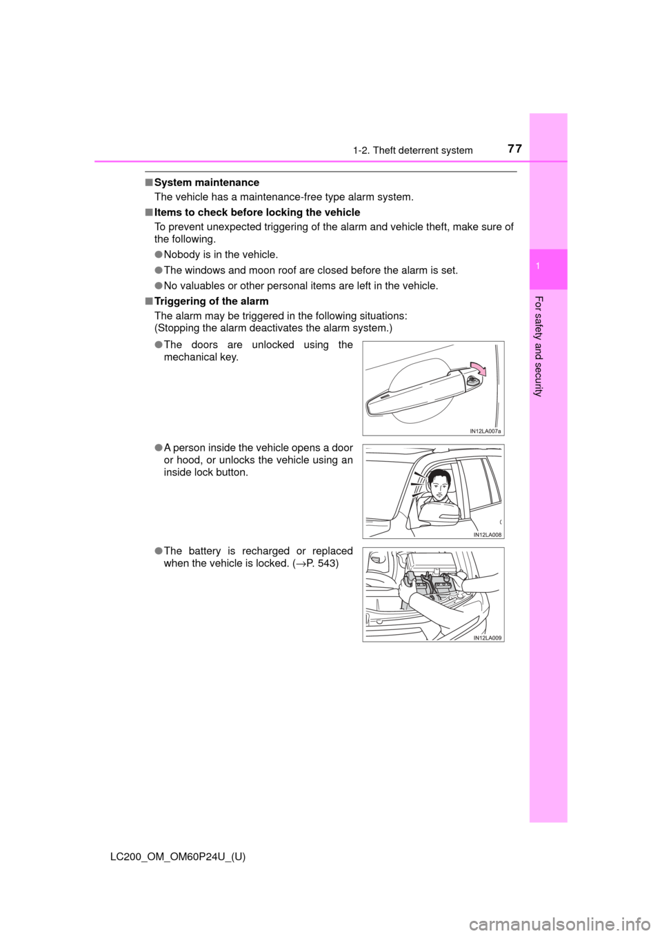
■ Triggering of the alarm
The alarm may be triggered in the following situations:
(Stopping the alarm deactivates the alarm system.)
●The doors are unlocked using the
mechanical key.
● A person inside the vehicle opens a door
or hood, or unlocks the vehicle using an
inside lock button.
● The battery is recharged or replaced
when the vehicle is locked. ( →P. 543)
Page 104 of 608

104
LC200_OM_OM60P24U_(U)
3-1. Key information
■When riding in an aircraft
When bringing an electronic key onto an aircraft, make sure you do not press
any buttons on the electronic key while inside the aircraft cabin. If you are
carrying an electronic key in your bag etc., ensure that the buttons are not
likely to be pressed accidentally. Pressing a button may cause the electronic
key to emit radio waves that could interfere with the operation of the aircraft.
■ Electronic key battery depletion
●The standard battery life is 1 to 2 years.
● If the battery becomes low, an alarm will sound in the cabin when the engine
stops.
● As the electronic key always receives radio waves, the battery will become
depleted even if the electronic key is not used. The following symptoms indi-
cate that the electronic key battery may be depleted. Replace the battery
when necessary. ( →P. 479)
• The smart key system or the wireless remote control does not operate.
• The detection area becomes smaller.
• The LED indicator on the key surface does not turn on.
● To avoid serious deterioration, do not leave the electronic key within 3 ft. (1
m) of the following electrical appl iances that produce a magnetic field:
•TVs
• Personal computers
• Recharging cellular phones or cordless phones
• Table lamps
• Induction cookers
■ Replacing the key battery
→P. 479
Page 107 of 608
LC200_OM_OM60P24U_(U)
1073-2. Opening, closing and locking the doors
3
Operation of each component
■Operation signals
Doors: A buzzer sounds and the emergency flashers flash to indicate that the
doors have been locked/unlocked. (Locked: once; Unlocked: twice)
Windows and moon roof: A buzzer sounds to indicate that the windows and
moon roof are operating.
■ Security feature
If a door is not opened within approximately 60 seconds after the vehicle is
unlocked, the security feature automatically locks the vehicle again.
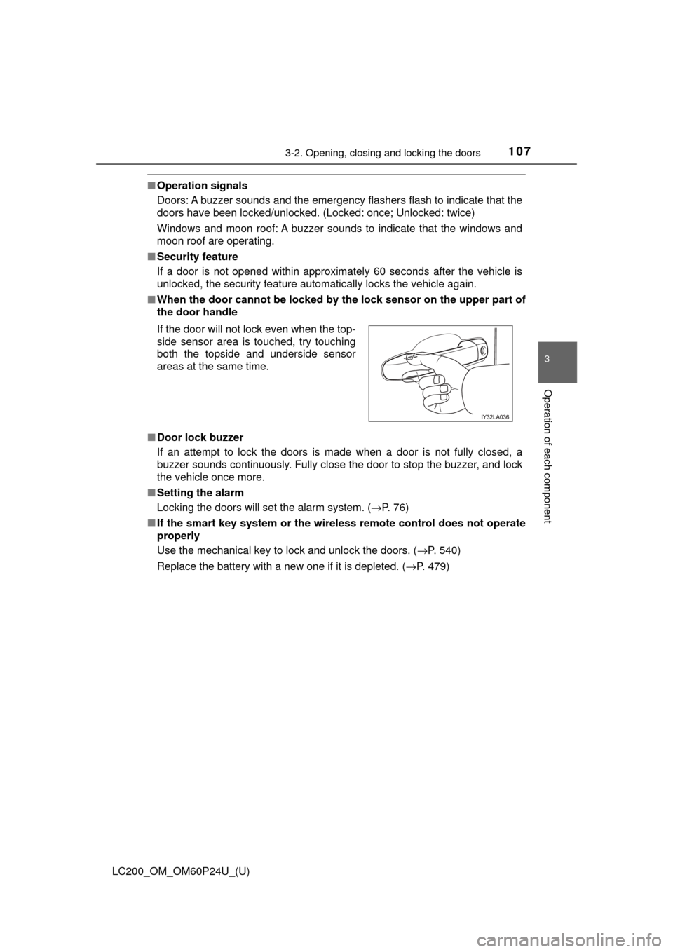
■ When the door ca nnot be locked by the lock sen sor on the upper part of
the door handle
■ Door lock buzzer
If an attempt to lock the doors is made when a door is not fully closed, a
buzzer sounds continuously. Fully close the door to stop the buzzer, and lock
the vehicle once more.
■ Setting the alarm
Locking the doors will set the alarm system. ( →P. 76)
■ If the smart key system or the wireless remote control does not operate
properly
Use the mechanical key to lock and unlock the doors. ( →P. 540)
Replace the battery with a new one if it is depleted. ( →P. 479)
If the door will not lock even when the top-
side sensor area is touched, try touching
both the topside and underside sensor
areas at the same time.
Page 429 of 608
LC200_OM_OM60P24U_(U)
4295-4. Using the other interior features
5
Interior features
■Languages
The Safety Connect response center will offer support in multiple languages.
The Safety Connect system will offer voice prompts in English and Spanish.
Please indicate your language of choice when enrolling.
■ When contacting th e response center
You may be unable to contact the response center if the network is busy.
■ Safety Connect backup battery depletion
An exclusive backup battery is built in to assist the Automatic Collision Notifi-
cation, which is activated when impact above a certain level is applied to the
vehicle, or when the airbags operate. This battery is a primary battery, and
cannot be recharged. The red LED indicator will flash to indicate that the bat-
tery should be replaced.
The backup battery will need to be replaced if the Automatic Collision Notifi-
cation operates for 60 seconds or more. For replacement, consult your Toy-
ota dealer.
When the engine switch is turned to IGNITION ON mode, the red indi-
cator light comes on for 2 seconds then turns off. Afterward, the green
indicator light comes on, indicating that the service is active.
The following indicator light pattern s indicate specific system usage
conditions:
● Green indicator light on = Active service
● Green indicator light flashing = Sa fety Connect call in process
● Red indicator light (except at vehicle start-up) = System malfunction
(contact your Toyota dealer)
● No indicator light (off) = Safety Connect service not active
Safety Connect LE D light Indicators
Page 479 of 608
479
LC200_OM_OM60P24U_(U)
6-3. Do-it-yourself maintenance
6
Maintenance and care
Electronic key battery
●Flathead screwdriver
● Small Phillips-head screwdriver
● Lithium battery (CR2032)
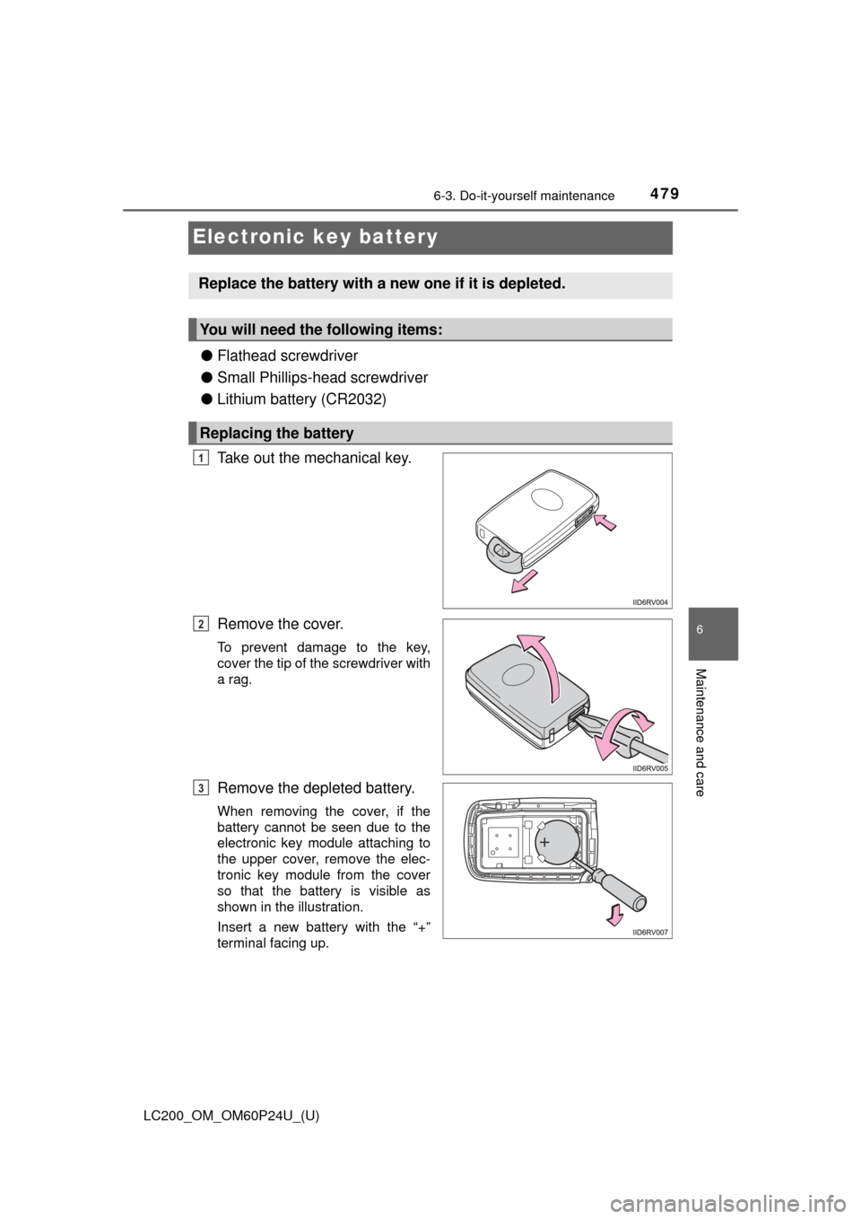
Take out the mechanical key.
Remove the cover.
To prevent damage to the key,
cover the tip of the screwdriver with
a rag.
Remove the depleted battery.
When removing the cover, if the
battery cannot be seen due to the
electronic key module attaching to
the upper cover, remove the elec-
tronic key module from the cover
so that the battery is visible as
shown in the illustration.
Insert a new battery with the “+”
terminal facing up.
Replace the battery with a new one if it is depleted.
You will need the following items:
Replacing the battery
1
2
3
Page 480 of 608
480
LC200_OM_OM60P24U_(U)
6-3. Do-it-yourself maintenance
■Use a CR2032 lithium battery
●Batteries can be purchased at your Toyota dealer, local electrical appliance
shops or camera stores.
● Replace only with the same or equivalent type recommended by the manu-
facturer.
● Dispose of used batteries according to the local laws.
■ If the electronic key battery is depleted
The following symptoms may occur:
●The smart key system and wireless remote control will not function properly.
● The operational range will be reduced.
WARNING
■ Removed battery and other parts
These parts are small and if swallowed by a child, they can cause choking.
Keep away from children. Failure to do so could result in death or serious
injury.
NOTICE
■For normal operation after replacing the battery
Observe the following precautions to prevent accidents:
● Always work with dry hands.
Moisture may cause the battery to rust.
● Do not touch or move any other component inside the remote control.
● Do not bend either of the battery terminals.
Page 541 of 608
5417-2. Steps to take in an emergency
LC200_OM_OM60P24U_(U)
7
When trouble arises
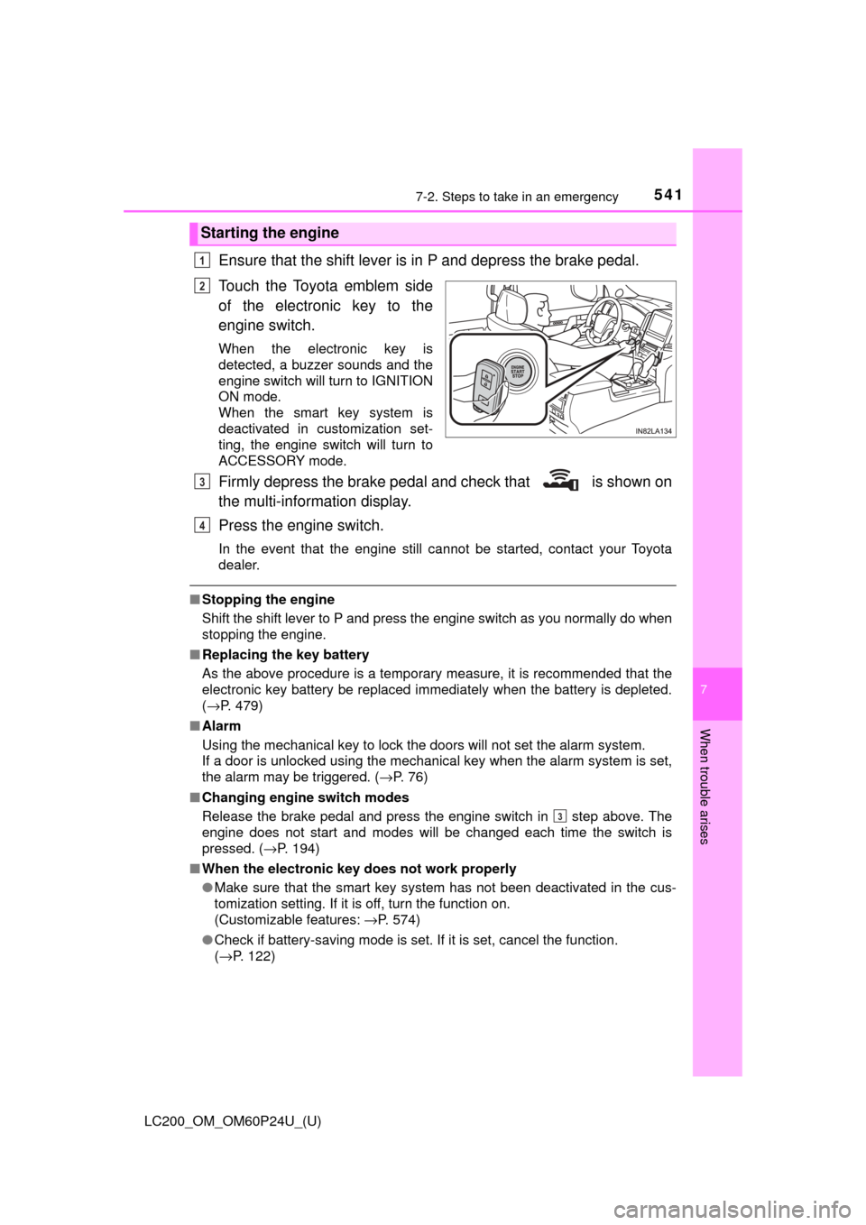
Ensure that the shift lever is in P and depress the brake pedal.
Touch the Toyota emblem side
of the electronic key to the
engine switch.
When the electronic key is
detected, a buzzer sounds and the
engine switch will turn to IGNITION
ON mode.
When the smart key system is
deactivated in customization set-
ting, the engine switch will turn to
ACCESSORY mode.
Firmly depress the brake pedal and check that is shown on
the multi-information display.
Press the engine switch.
In the event that the engine still cannot be started, contact your Toyota
dealer.
■Stopping the engine
Shift the shift lever to P and press the engine switch as you normally do when
stopping the engine.
■ Replacing the key battery
As the above procedure is a temporary measure, it is recommended that the
electronic key battery be replaced immediately when the battery is depleted.
(→P. 479)
■ Alarm
Using the mechanical key to lock the doors will not set the alarm system.
If a door is unlocked using the mechanical key when the alarm system is set,
the alarm may be triggered. ( →P. 76)
■ Changing engine switch modes
Release the brake pedal and press the engine switch in step above. The
engine does not start and modes will be changed each time the switch is
pressed. ( →P. 194)
■ When the electronic key does not work properly
●Make sure that the smart key system has not been deactivated in the cus-
tomization setting. If it is off, turn the function on.
(Customizable features: →P. 574)
● Check if battery-saving mode is set. If it is set, cancel the function.
(→P. 122)
Starting the engine
1
2
3
4
3
Page 569 of 608
LC200_OM_OM60P24U_(U)
5698-1. Specifications
8
Vehicle specifications
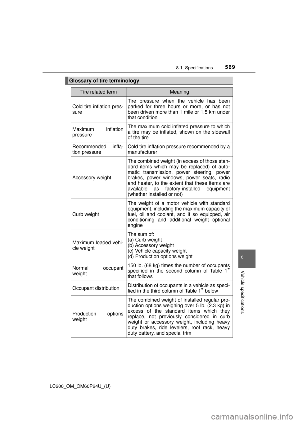
Glossary of tire terminology
Tire related termMeaning
Cold tire inflation pres-
sure
Tire pressure when the vehicle has been
parked for three hours or more, or has not
been driven more than 1 mile or 1.5 km under
that condition
Maximum inflation
pressureThe maximum cold inflated pressure to which
a tire may be inflated, shown on the sidewall
of the tire
Recommended infla-
tion pressureCold tire inflation pressure recommended by a
manufacturer
Accessory weight
The combined weight (in excess of those stan-
dard items which may be replaced) of auto-
matic transmission, power steering, power
brakes, power windows, power seats, radio
and heater, to the extent that these items are
available as factory-installed equipment
(whether installed or not)
Curb weight
The weight of a motor vehicle with standard
equipment, including the maximum capacity of
fuel, oil and coolant, and if so equipped, air
conditioning and additional weight optional
engine
Maximum loaded vehi-
cle weight
The sum of:
(a) Curb weight
(b) Accessory weight
(c) Vehicle capacity weight
(d) Production options weight
Normal occupant
weight150 lb. (68 kg) times the number of occupants
specified in the second column of Table 1
*
that follows
Occupant distributionDistribution of occupants in a vehicle as speci-
fied in the third column of Table 1
* below
Production options
weight
The combined weight of installed regular pro-
duction options weighing over 5 lb. (2.3 kg) in
excess of the standard items which they
replace, not previously considered in curb
weight or accessory weight, including heavy
duty brakes, ride levelers, roof rack, heavy
duty battery, and special trim