Page 97 of 608

LC200_OM_OM60P24U_(U)
972. Instrument cluster
2
Instrument cluster
■Tire inflation pressure
●It may take a few minutes to display the tire inflation pressure after the
engine switch is turned to IGNITION ON mode. It may also take a few
minutes to display the tire inflation pressure after inflation pressure has
been adjusted.
●“---” may be displayed if the tire information cannot be determined due to
unfavorable radio wave conditions.
●Tire inflation pressure changes with temperature. The displayed values
may also be different from the values measured using a tire pressure
gauge.
■ When setting up the display
Stop the vehicle in a safe place, apply the parking brake, and shift the shift
lever to P
■ Suspension of the settings display
In the following situations, the settings display using the meter control
switches will be suspended.
●When a warning message appears on the multi-information display
● When the vehicle begins to move
■ Liquid crystal display
Small spots or light spots may appear on the display. This phenomenon is
characteristic of liquid crystal displays, and there is no problem continuing to
use the display.
WARNING
■Caution for use while driving
For safety, avoid operating the meter control switch while driving as much
as possible, and do not look continuously at the multi-information display
while driving. Stop the vehicle and operate the meter control switch. Failure
to do so may cause a steering wheel operation error, resulting in an unex-
pected accident.
■ Cautions while setting up the display
As the engine needs to be running during setting up the display, ensure that
the vehicle is parked in a place with adequate ventilation. In a closed area
such as a garage, exhaust gases including harmful carbon monoxide (CO)
may collect and enter the vehicle. This may lead to death or a serious
health hazard.
NOTICE
■While setting up the display
To prevent battery discharge, ensure that the engine is running while setting
up the display features.
Page 98 of 608
98
LC200_OM_OM60P24U_(U)
2. Instrument cluster
Fuel consumption information
Press the “INFO/APPS” button, and then select “Fuel Consumption”
on the screen.
Reset the trip information data
Previous fuel consumption per
minute
Current fuel consumption
Average vehicle speed
Elapsed time
Cruising range
Average fuel consumption for the past 15 minutes is divided by color
into past averages and averages at tained since the engine switch was
last turned to IGNITION ON mode. Use the displayed average fuel
consumption as a reference.
These images are examples only, an d may vary slightly from actual
conditions.
The fuel consumption information can be displayed on the navi-
gation system or multimedia system screen.
Display the trip information or past record screen
Trip information
1
2
3
4
5
6
Page 99 of 608

LC200_OM_OM60P24U_(U)
992. Instrument cluster
2
Instrument cluster
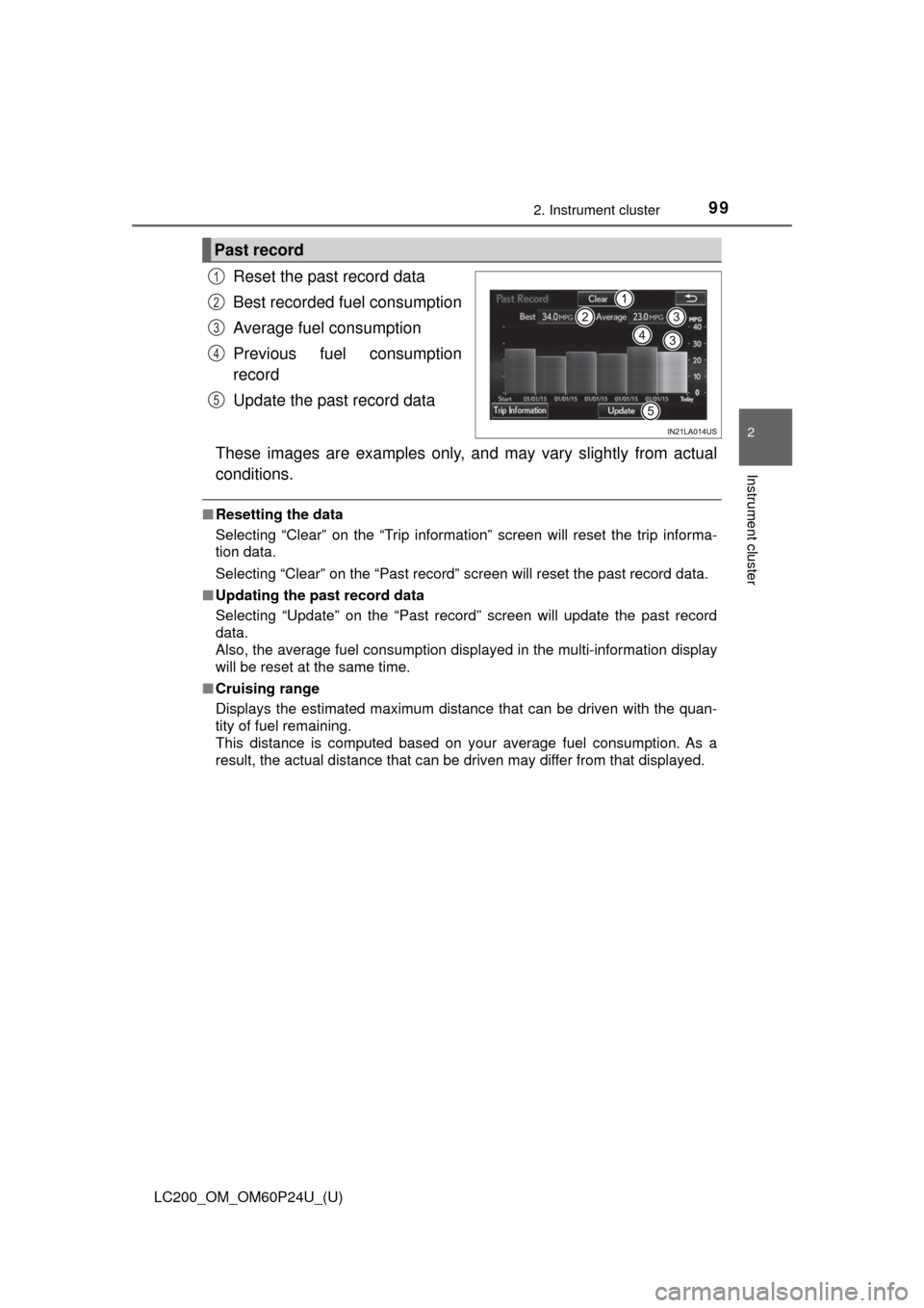
Reset the past record data
Best recorded fuel consumption
Average fuel consumption
Previous fuel consumption
record
Update the past record data
These images are examples only, an d may vary slightly from actual
conditions.
■ Resetting the data
Selecting “Clear” on the “Trip information” screen will reset the trip informa-
tion data.
Selecting “Clear” on the “Past record” screen will reset the\
past record data.
■ Updating the past record data
Selecting “Update” on the “Past record” screen will update the past record
data.
Also, the average fuel consumption displa yed in the multi-information display
will be reset at the same time.
■ Cruising range
Displays the estimated maximum distance that can be driven with the quan-
tity of fuel remaining.
This distance is computed based on your average fuel consumption. As a
result, the actual distance that can be driven may differ from that displayed.
Past record
1
2
3
4
5
Page 103 of 608

LC200_OM_OM60P24U_(U)
1033-1. Key information
3
Operation of each component
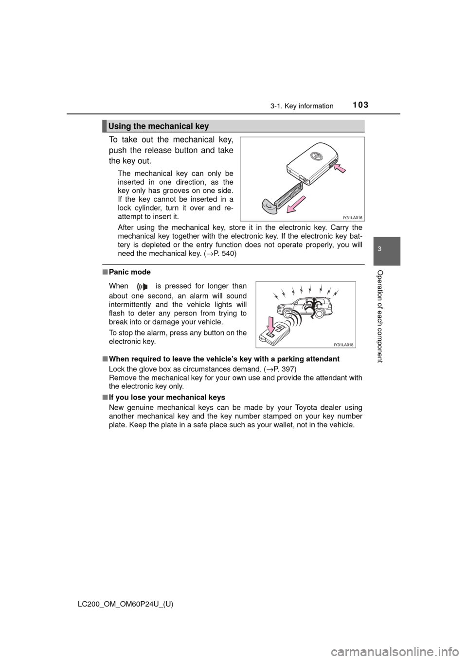
To take out the mechanical key,
push the release button and take
the key out.
The mechanical key can only be
inserted in one direction, as the
key only has grooves on one side.
If the key cannot be inserted in a
lock cylinder, turn it over and re-
attempt to insert it.
After using the mechanical key, store it in the electronic key. Carry the
mechanical key together with the electronic key. If the electronic key bat-
tery is depleted or the entry function does not operate properly, you will
need the mechanical key. (→P. 540)
■Panic mode
■ When required to leave the vehicle’s key with a parking attendant
Lock the glove box as circumstances demand. ( →P. 397)
Remove the mechanical key for your own use and provide the attendant with
the electronic key only.
■ If you lose your mechanical keys
New genuine mechanical keys can be made by your Toyota dealer using
another mechanical key and the key number stamped on your key number
plate. Keep the plate in a safe place such as your wallet, not in the vehicle.
Using the mechanical key
When is pressed for longer than
about one second, an alarm will sound
intermittently and the vehicle lights will
flash to deter any person from trying to
break into or damage your vehicle.
To stop the alarm, press any button on the
electronic key.
Page 112 of 608

112
LC200_OM_OM60P24U_(U)
3-2. Opening, closing and locking the doors
■Changing the door unlock function setting
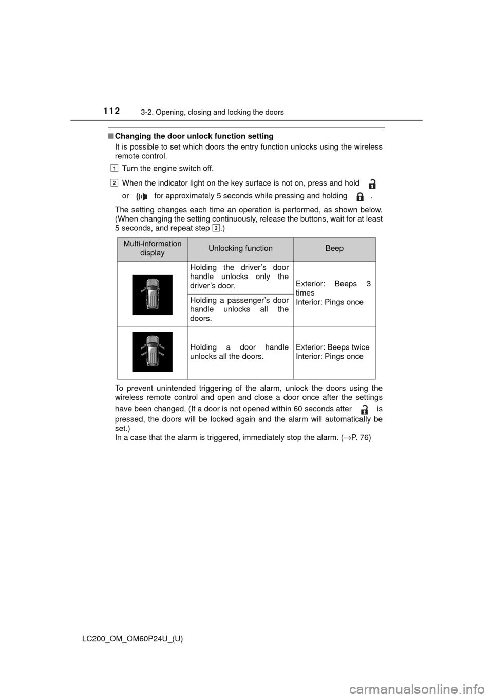
It is possible to set which doors the entry function unlocks using the wireless
remote control.
Turn the engine switch off.
When the indicator light on the key surface is not on, press and hold
or for approximately 5 seconds while pressing and holding .
The setting changes each time an operation is performed, as shown below.
(When changing the setting continuously, release the buttons, wait for at least
5 seconds, and repeat step .)
To prevent unintended triggering of the alarm, unlock the doors using the
wireless remote control and open and close a door once after the settings
have been changed. (If a door is not opened within 60 seconds after is
pressed, the doors will be locked again and the alarm will automatically be
set.)
In a case that the alarm is triggered, immediately stop the alarm. ( →P. 76)
1
2
2
Multi-information
displayUnlocking functionBeep
Holding the driver’s door
handle unlocks only the
driver’s door.
Exterior: Beeps 3
times
Interior: Pings once
Holding a passenger’s door
handle unlocks all the
doors.
Holding a door handle
unlocks all the doors.Exterior: Beeps twice
Interior: Pings once
Page 119 of 608

LC200_OM_OM60P24U_(U)
1193-2. Opening, closing and locking the doors
3
Operation of each component
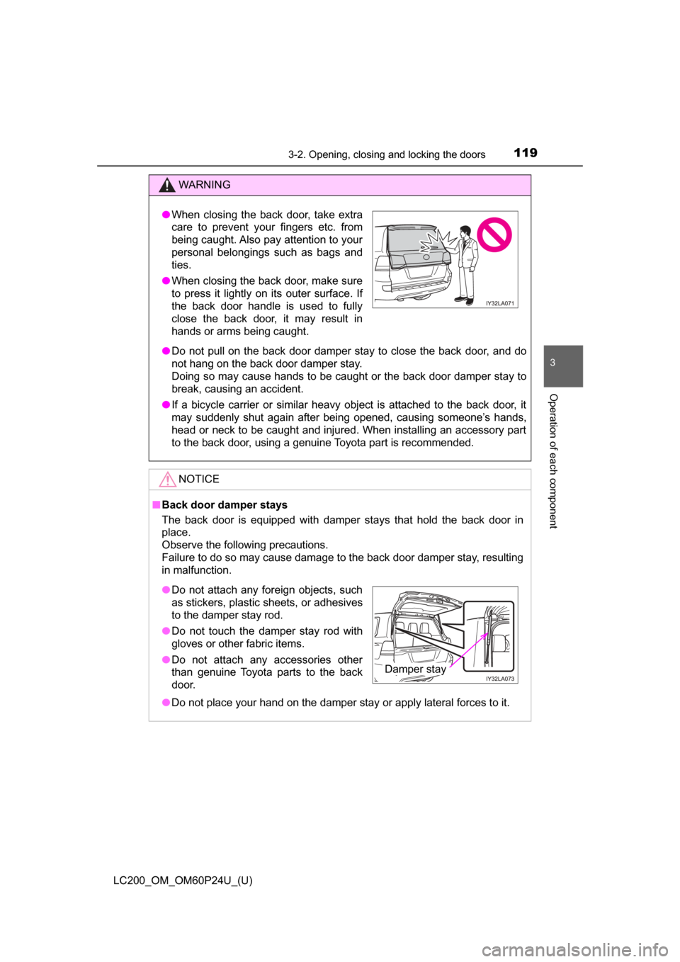
WARNING
●Do not pull on the back door damper stay to close the back door, and do
not hang on the back door damper stay.
Doing so may cause hands to be caught or the back door damper stay to
break, causing an accident.
● If a bicycle carrier or similar heavy object is attached to the back door, it
may suddenly shut again after being opened, causing someone’s hands,
head or neck to be caught and injured. When installing an accessory part
to the back door, using a genuine Toyota part is recommended.
NOTICE
■ Back door damper stays
The back door is equipped with damper stays that hold the back door in
place.
Observe the following precautions.
Failure to do so may cause damage to the back door damper stay, resulting
in malfunction.
● Do not place your hand on the damper stay or apply lateral forces to it.
●When closing the back door, take extra
care to prevent your fingers etc. from
being caught. Also pay attention to your
personal belongings such as bags and
ties.
● When closing the back door, make sure
to press it lightly on its outer surface. If
the back door handle is used to fully
close the back door, it may result in
hands or arms being caught.
●Do not attach any foreign objects, such
as stickers, plastic sheets, or adhesives
to the damper stay rod.
● Do not touch the damper stay rod with
gloves or other fabric items.
● Do not attach any accessories other
than genuine Toyota parts to the back
door.
Damper stay
Page 124 of 608

124
LC200_OM_OM60P24U_(U)
3-2. Opening, closing and locking the doors
●If the door handle becomes wet while the electronic key is within the effec-
tive range, the door may lock and unlock repeatedly. In this case, follow the
following correction procedures to wash the vehicle.
• Place the electronic key in a location 6 ft. (2 m) or more away from the
vehicle. (Take care to ensure that the key is not stolen.)
• Set electronic key to battery-saving mode to disable the smart key sys- tem. ( →P. 122)
● If the electronic key is inside the vehicle and a door handle becomes wet
during a car wash, a message may be shown on the multi-information dis-
play and a buzzer will sound outside the vehicle. To turn off the alarm, lock
all the doors.
● The lock sensor may not work properly if it comes into contact with ice,
snow, mud, etc. Clean the lock sensor and attempt to operate it again, or
use the lock sensor on the lower part of the door handle.
● If there is another electronic key in the detection area, it may take slightly
longer to unlock the doors after the door handle is gripped or back door
unlock switch is pressed.
● A sudden approach to the effective range or door handle may prevent the
doors from being unlocked. In this case, return the door handle to the origi-
nal position and check that the doors unlock before pulling the door handle
again.
■ When the vehicle is not driven for extended periods
●To prevent theft of the vehicle, do not leave the electronic key within 6 ft.
(2 m) of the vehicle.
● The smart key system can be deactivated in advance. ( →P. 574)
■ To operate the system properly
Make sure to carry the electronic key when operating the system. Do not get
the electronic key too close to the vehicle when operating the system from the
outside of the vehicle.
Depending on the position and holding condition of the electronic key, the key
may not be detected correctly and the system may not operate properly. (The
alarm may go off accidentally, or the door lock prevention function may not
operate.)
Page 127 of 608
127
LC200_OM_OM60P24U_(U)
3-3. Adjusting the seats
3
Operation of each component
Front seats
Seat position control switch
Seatback angle control switch
Seat cushion (front) angle control switch
Vertical height control switch
Lumber support control switch (driver’s side only)
When the occupant’s lower back
presses against the seatback
during a rear-end collision, the
head restraint moves slightly for-
ward and upward to help reduce
the risk of whiplash on the seat
occupant.
Adjustment procedure
Active head restraints
1
2
3
4
5