Page 5 of 608

5
1
8 7
6
5
4
3
2
LC200_OM_OM60P24U_(U)
9
6-1. Maintenance and careCleaning and protecting the vehicle exterior .......... 434
Cleaning and protecting the vehicle interior ........... 437
6-2. Maintenance Maintenance requirements ................... 440
General maintenance ........ 443
Emission inspection and maintenance (I/M)
programs ......................... 446
6-3. Do-it-yourself maintenance Do-it-yourself service precautions ..................... 447
Hood.................................. 449
Engine compartment ......... 450
Tires .................................. 463
Tire inflation pressure........ 472
Wheels .............................. 475
Air conditioning filter .......... 477
Electronic key battery ........ 479
Checking and replacing fuses ............................... 481
Headlight aim .................... 485
Light bulbs ......................... 487 7-1. Essential information
Emergency flashers ........... 500
If your vehicle has to be stopped in
an emergency.................. 501
7-2. Steps to take in an emergency
If your vehicle needs to be towed ...................... 502
If you think something is wrong............................... 508
Fuel pump shut off system ............................. 509
If a warning light turns on or a warning buzzer
sounds ............................. 510
If a warning message is displayed ......................... 519
If you have a flat tire .......... 524
If the engine will not start ................................. 538
If the electronic key does not operate properly ........ 540
If the vehicle battery is discharged ....................... 543
If your vehicle overheats.... 546
If the vehicle becomes stuck ................................ 549
6Maintenance and care7When trouble arises
Page 76 of 608

761-2. Theft deterrent system
LC200_OM_OM60P24U_(U)
Alarm
The alarm uses light and sound to give an alert when an intrusion is
detected.
The alarm is triggered in the following situations when the alarm is
set:
●A locked door is unlocked or opened in any way other than using
the entry function or wireless re mote control. (The doors will lock
again automatically.)
● The hood is opened.
● The battery is reconnected.
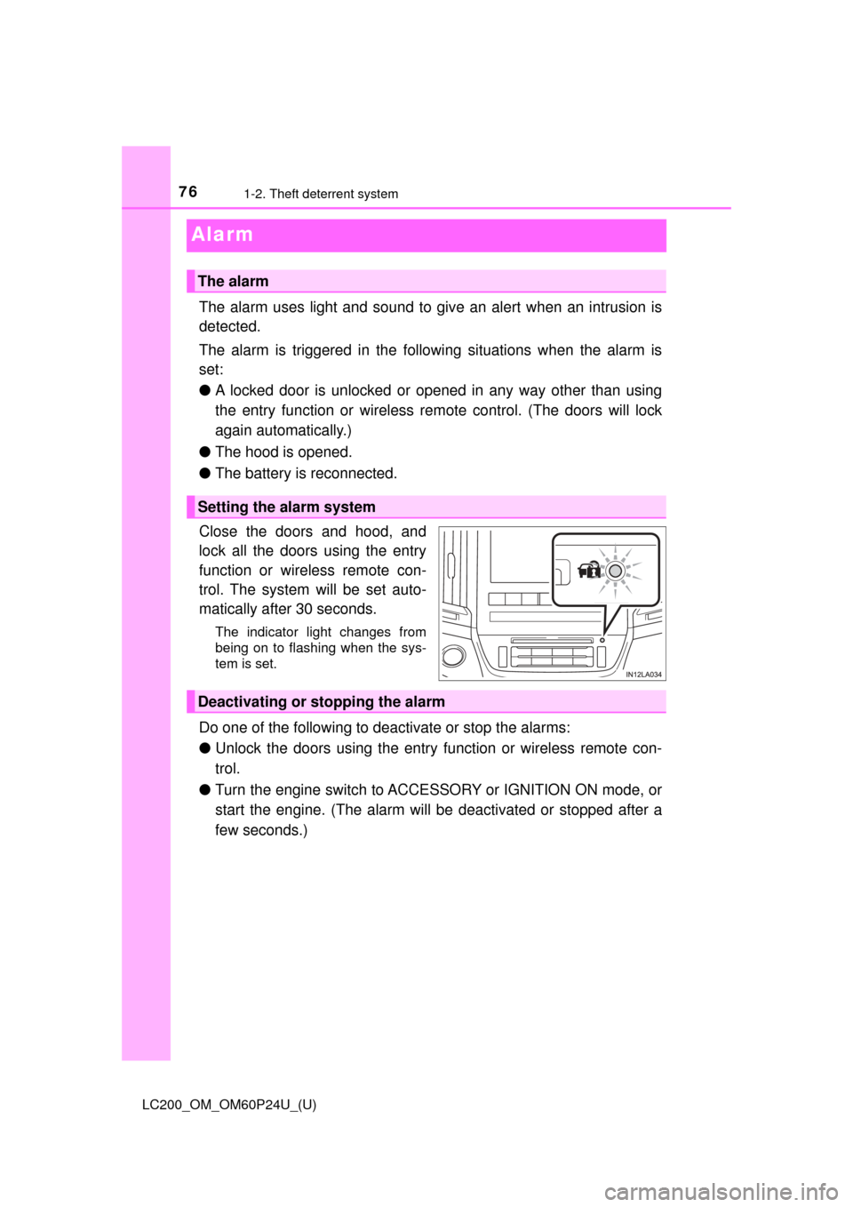
Close the doors and hood, and
lock all the doors using the entry
function or wireless remote con-
trol. The system will be set auto-
matically after 30 seconds.
The indicator light changes from
being on to flashing when the sys-
tem is set.
Do one of the following to d eactivate or stop the alarms:
● Unlock the doors using the entry function or wireless remote con-
trol.
● Turn the engine switch to ACCESSORY or IGNITION ON mode, or
start the engine. (The alarm will be deactivated or stopped after a
few seconds.)
The alarm
Setting the alarm system
Deactivating or stopping the alarm
Page 77 of 608
771-2. Theft deterrent system
LC200_OM_OM60P24U_(U)
1
For safety and security
■System maintenance
The vehicle has a maintenance-free type alarm system.
■ Items to check before locking the vehicle
To prevent unexpected triggering of the alarm and vehicle theft, make sure of
the following.
●Nobody is in the vehicle.
● The windows and moon roof are closed before the alarm is set.
● No valuables or other personal items are left in the vehicle.
■ Triggering of the alarm
The alarm may be triggered in the following situations:
(Stopping the alarm deactivates the alarm system.)
●The doors are unlocked using the
mechanical key.
● A person inside the vehicle opens a door
or hood, or unlocks the vehicle using an
inside lock button.
● The battery is recharged or replaced
when the vehicle is locked. ( →P. 543)
Page 78 of 608
781-2. Theft deterrent system
LC200_OM_OM60P24U_(U)■
Alarm-operated door lock
In the following cases, depending on the situation, the door may automatically
lock to prevent improper entry into the vehicle:
●When a person remaining in the vehicle unlocks the door and the alarm is
activated.
● While the alarm is activated, a person remaining in the vehicle unlocks the
door.
● When recharging or replacing the battery.
NOTICE
■To ensure the system operates correctly
Do not modify or remove the system. If modified or removed, the proper
operation of the system cannot be guaranteed.
Page 88 of 608

88
LC200_OM_OM60P24U_(U)
2. Instrument cluster
NOTICE
■To prevent damage to the engine and its components
● Do not let the indicator needle of the tachometer enter the red zone, which
indicates the maximum engine speed.
● The engine may be overheating if the engine coolant temperature gauge is
in the red zone (H). In this case, immediately stop the vehicle in a safe
place, and check the engine after it has cooled completely. (→ P. 546)
■ Voltmeter
When the voltmeter indicates 19 V or higher or 9 V or lower while the engine
is running, there may be a battery or charging system malfunction. Have the
vehicle inspected at your Toyota dealer.
■ Engine oil pressure gauge
When the value of the engine oil pressure gauge drops while the engine is
running, stop the vehicle in a safe place immediately and check the amount
of engine oil. ( →P. 452)
When the oil pressure drops even though the engine oil amount has not
decreased, or if the oil pressure does not increase when engine oil is
added, contact your Toyota dealer, as there may be a problem with the lubri-
cation system.
Page 94 of 608

94
LC200_OM_OM60P24U_(U)
2. Instrument cluster
Items displayed can be switched by operating up and down.
■Front tire angle (if equipped)
Displays the direction of the front tires.
The tire direction is displayed in 3 stages for both left and right, in
accordance with the angle of the tire.
If a battery terminal is disconnected and reconnected, the display may
be disabled temporarily. After driving the vehicle for a while, the display
will be enabled.
■
Tire inflation pressure (if equipped)
Displays inflation pressure of each tire
The inflation pressure of the spare tire will be displayed.
■Oil maintenance
Displays the remaining distance before the next maintenance is
required.
The settings of some features can be changed by using the meter
control switches.
■Setting procedure On the setting screen, choose the desired item using , and
then press .
• For functions that can be enabled or disabled, the function switches between on and off each time is pressed.
• For functions that allow to select operation contents, display con-
tents, etc., the setting screen is displayed.
Select the desired setting by operating , and then press
.
To stop the selection, press to return to the previous screen.
Vehicle information
Settings display
1
2
Page 96 of 608

96
LC200_OM_OM60P24U_(U)
2. Instrument cluster
• Accent colorSelect to change the accent colors on the screen, such as the
cursor color.
• Initialization Select to reset the me ter display settings.
*: If equipped
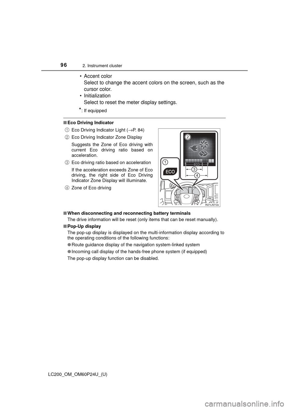
■Eco Driving Indicator
■ When disconnecting and reco nnecting battery terminals
The drive information will be reset (only items that can be reset manually).
■ Pop-Up display
The pop-up display is displayed on the multi-information display according to
the operating conditions of the following functions:
●Route guidance display of the navigation system-linked system
● Incoming call display of the hands-free phone system (if equipped)
The pop-up display function can be disabled. Eco Driving Indicator Light (
→P. 84)
Eco Driving Indicator Zone Display
Suggests the Zone of Eco driving with
current Eco driving ratio based on
acceleration.
Eco driving ratio based on acceleration
If the acceleration exceeds Zone of Eco
driving, the right side of Eco Driving
Indicator Zone Display will illuminate.
Zone of Eco driving
1
2
3
4
Page 97 of 608

LC200_OM_OM60P24U_(U)
972. Instrument cluster
2
Instrument cluster
■Tire inflation pressure
●It may take a few minutes to display the tire inflation pressure after the
engine switch is turned to IGNITION ON mode. It may also take a few
minutes to display the tire inflation pressure after inflation pressure has
been adjusted.
●“---” may be displayed if the tire information cannot be determined due to
unfavorable radio wave conditions.
●Tire inflation pressure changes with temperature. The displayed values
may also be different from the values measured using a tire pressure
gauge.
■ When setting up the display
Stop the vehicle in a safe place, apply the parking brake, and shift the shift
lever to P
■ Suspension of the settings display
In the following situations, the settings display using the meter control
switches will be suspended.
●When a warning message appears on the multi-information display
● When the vehicle begins to move
■ Liquid crystal display
Small spots or light spots may appear on the display. This phenomenon is
characteristic of liquid crystal displays, and there is no problem continuing to
use the display.
WARNING
■Caution for use while driving
For safety, avoid operating the meter control switch while driving as much
as possible, and do not look continuously at the multi-information display
while driving. Stop the vehicle and operate the meter control switch. Failure
to do so may cause a steering wheel operation error, resulting in an unex-
pected accident.
■ Cautions while setting up the display
As the engine needs to be running during setting up the display, ensure that
the vehicle is parked in a place with adequate ventilation. In a closed area
such as a garage, exhaust gases including harmful carbon monoxide (CO)
may collect and enter the vehicle. This may lead to death or a serious
health hazard.
NOTICE
■While setting up the display
To prevent battery discharge, ensure that the engine is running while setting
up the display features.