2017 TOYOTA LAND CRUISER Code 49
[x] Cancel search: Code 49Page 423 of 608
LC200_OM_OM60P24U_(U)
4235-4. Using the other interior features
5
Interior features
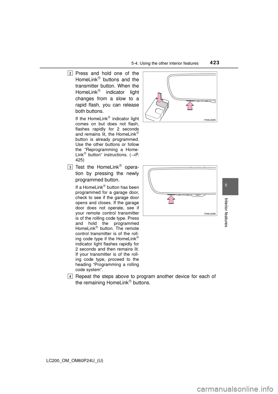
Press and hold one of the
HomeLink buttons and the
transmitter button. When the
HomeLink
indicator light
changes from a slow to a
rapid flash, you can release
both buttons.
If the HomeLink indicator light
comes on but does not flash,
flashes rapidly for 2 seconds
and remains lit, the HomeLink
button is already programmed.
Use the other buttons or follow
the “Reprogramming a Home-
Link
button” instructions. ( →P.
425)
Test the HomeLink opera-
tion by pressing the newly
programmed button.
If a HomeLink button has been
programmed for a garage door,
check to see if the garage door
opens and closes. If the garage
door does not operate, see if
your remote control transmitter
is of the rolling code type. Press
and hold the programmed
HomeLink
button. The remote
control transmitter is of the roll-
ing code type if the HomeLink
indicator light flashes rapidly for
2 seconds and then remains lit.
If your transmitter is of the roll-
ing code type, proceed to the
heading “Programming a rolling
code system”.
Repeat the steps above to program another device for each of
the remaining HomeLink buttons.
2
3
4
Page 424 of 608

424
LC200_OM_OM60P24U_(U)
5-4. Using the other interior features
■Programming a rolling code system
If your device is rolling code eq uipped, follow the steps under the
heading “Programming HomeLink
” before proceeding with the
steps listed below.
Locate the learn button on the ceiling mounted garage door
opener motor. The exact location and color of the button may
vary by brand of garage door opener motor.
Refer to the operation manual supplied with the garage door opener
motor for the location of the learn button.
Press the learn button.
Following this step, you have 30 seconds in which to initiate below.
Press and hold the vehicle’s programmed HomeLink button for
2 seconds and release it. Repea t this step once again. The
garage door may open.
If the garage door opens, the programming process is complete. If the
door does not open, press and release the button a third time. This third
press and release will complete the programming process by opening
the garage door.
The ceiling mounted garage door opener motor should now recognize
the HomeLink
signal and operate the garage door.
Repeat the steps above to program another rolling code system
for any of the remaining HomeLink buttons.
■Programming an entry gate (for U.S.A. owners)/Programming
all devices in the Canadian market
Place your transmitter 1 to 3 in. (25 to 75 mm) away from the sur-
face of the HomeLink
.
Keep the HomeLink indicator light in view while programming.
Press and hold the selected HomeLink button.
Repeatedly press and release (cyc le) the device’s remote control
button for 2 seconds each until is completed.
When the indicator light on the HomeLink
compatible trans-
ceiver starts to flash rapidly, release the buttons.
Test the operation of the HomeLink
by pressing the newly pro-
grammed button. Check to see if the gate/device operates cor-
rectly.
Repeat the steps above to program another device for each of
the remaining HomeLink
buttons.
1
2
3
3
4
1
2
3
4
4
5
6
Page 446 of 608
446
LC200_OM_OM60P24U_(U)
6-2. Maintenance
Emission inspection and maintenance (I/M)
programs
The OBD system determin es that a problem exists somewhere in the
emission control system. Your vehi cle may not pass the I/M test and
may need to be repaired. Contact your Toyota dealer to service the
vehicle.
● When the battery is disconnected or discharged
Readiness codes that are set duri ng ordinary driving are erased.
Also, depending on your driving habits, the readiness codes may
not be completely set.
● When the fuel tank cap is loose
The malfunction indicator lamp comes on indicating a temporary
malfunction and your vehicle may not pass the I/M test.
The error code in the OBD system will not be cleared unless the vehi-
cle is driven 40 or more times.
Contact your Toyota dealer to prepare the vehicle for re-testing.
Some states have vehicle emission inspection programs which
include OBD (On Board Diagnos tics) checks. The OBD system
monitors the operation of the emission control system.
If the malfunction indicator lamp comes on
Your vehicle may not pass the I/M test in the following situations:
When the malfunction indicator la mp still remains on after sev-
eral driving trips
If your vehicle does not pass the I/M test
Page 464 of 608
464
LC200_OM_OM60P24U_(U)
6-3. Do-it-yourself maintenance
Your Toyota is equipped with a tire pressure warning system that uses
tire pressure warning valves and transmitters to detect low tire infla-
tion pressure before serious problems arise.
● If the tire pressure drops below a predetermined level, the driver is
warned by a screen display and a warning light. ( →P. 512)
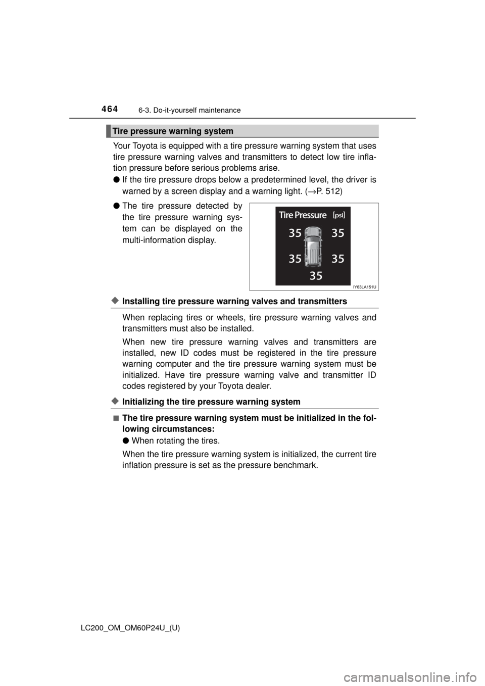
● The tire pressure detected by
the tire pressure warning sys-
tem can be displayed on the
multi-information display.
◆Installing tire pressure warning valves and transmitters
When replacing tires or wheels, tire pressure warning valves and
transmitters must also be installed.
When new tire pressure warning valves and transmitters are
installed, new ID codes must be registered in the tire pressure
warning computer and the tire pr essure warning system must be
initialized. Have tire pressure warning valve and transmitter ID
codes registered by your Toyota dealer.
◆Initializing the tire pressure warning system
■The tire pressure warning system must be initialized in the fol-
lowing circumstances:
● When rotating the tires.
When the tire pressure warning system is initialized, the current tire
inflation pressure is set as the pressure benchmark.
Tire pressure warning system
Page 465 of 608
LC200_OM_OM60P24U_(U)
4656-3. Do-it-yourself maintenance
6
Maintenance and care
■How to initialize the tire pressure warning systemPark the vehicle in safe plac e and turn the engine switch off.
Initialization cannot be performed while the vehicle is moved.
Adjust the tire inflation pressure to the specified cold tire inflation
pressure level. ( →P. 558)
Make sure to adjust the tire pressu re to the specified cold tire infla-
tion pressure level. The tire pressure warning system will operate
based on this pressure level.
Turn the engine switch to IGNITION ON mode.
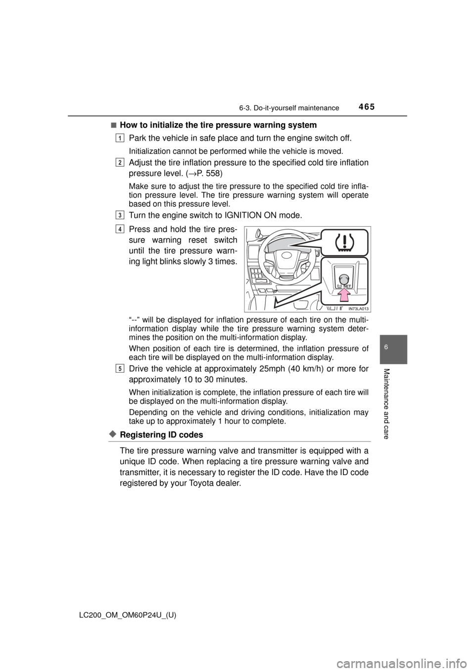
Press and hold the tire pres-
sure warning reset switch
until the tire pressure warn-
ing light blinks slowly 3 times.
“--” will be displayed for inflation pressure of each tire on the multi-
information display while the tire pressure warning system deter-
mines the position on the multi-information display.
When position of each tire is determined, the inflation pressure of
each tire will be displayed on the multi-information display.
Drive the vehicle at approximatel y 25mph (40 km/h) or more for
approximately 10 to 30 minutes.
When initialization is co mplete, the inflation pre ssure of each tire will
be displayed on the multi-information display.
Depending on the vehicle and driving conditions, initialization may
take up to approximately 1 hour to complete.
◆Registering ID codes
The tire pressure warning valve and transmitter is equipped with a
unique ID code. When replacing a tire pressure warning valve and
transmitter, it is necessary to register the ID code. Have the ID code
registered by your Toyota dealer.
1
2
3
4
5
Page 466 of 608

466
LC200_OM_OM60P24U_(U)
6-3. Do-it-yourself maintenance
■When to replace your vehicle’s tires
Tires should be replaced if:
●The treadwear indicators are showing on a tire.
●You have tire damage such as cuts, splits, cracks deep enough to
expose the fabric, and bulges indicating internal damage
●A tire goes flat repeatedly or cannot be properly repaired due to the size
or location of a cut or other damage
If you are not sure, consult with your Toyota dealer.
■Replacing tires and wheels
If the ID code of the tire pressure warning valve and transmitter is not reg-
istered, the tire pressure warning system will not work properly. After driv-
ing for about 20 minutes, the tire pressure warning light blinks for 1
minute and stays on to indicate a system malfunction.
■Tire life
Any tire over 6 years old must be checked by a qualified technician even
if it has seldom or never been used or damage is not obvious.
■Routine tire inflation pressure checks
The tire pressure warning system does not replace routine tire inflation
pressure checks. Make su re to check tire inflation pressure as part of
your routine of daily vehicle checks.
■Maximum load of tire
Check that the number given by dividing the maximum load by 1.10 of the
replacement tire is greater than 1/ 2 of the Gross Axle Weight Ratings
(GAWR) of either the front axle or the rear axle, whichever is greater.
For the GAWR, see the Certification
Label. For the maximum load of the tire,
see the load limit at maximum cold tire
inflation pressure mentioned on the
sidewall of the tire. ( →P. 563)
Page 468 of 608

468
LC200_OM_OM60P24U_(U)
6-3. Do-it-yourself maintenance
■If the tread on snow tires wears down below 0.16 in. (4 mm)
The effectiveness of the tires as snow tires is lost.
■Initializing the tire pressure warning system
initialize the system with the tire inflat ion pressure adjusted to the speci-
fied level.
■Situations in which the tire pressure warning system may not oper-
ate properly
●In the following cases, the tire pr essure warning system may not operate
properly.
• If non-genuine Toyota wheels are used.
• A tire has been replaced with a tire that is not an OE (Original Equip- ment) tire.
• A tire has been replaced with a tire that is not of the specified size.
• Tire chains etc. are equipped.
• An auxiliary-supported run- flat tire is equipped.
• If a window tint that affects the radio wave signals is installed.
• If there is a lot of snow or ice on the vehicle, particularly around the
wheels or wheel housings.
• If the spare tire is in a location subject to poor radio wave signal reception.
• If a large metallic object which ca n interfere with signal reception is
put near the spare tire.
• If tires not equipped with the tire pressure warning valves and trans-
mitters are used.
• If the ID code on the tire pressure warning valves and transmitters is not registered in the tire pressure warning computer.
●Performance may be affected in the following situations.
• Near a TV tower, electric power plant, gas station, radio station, largedisplay, airport or other facility that generates strong radio waves or
electrical noise
• When carrying a portable radio, cellular phone, cordless phone or other wireless communication device
●When the vehicle is parked, the time taken for the warning to start or go
off could be extended.
●When tire inflation pressure declines rapidly for example when a tire has
burst, the warning may not function.
Page 564 of 608
564
LC200_OM_OM60P24U_(U)
8-1. Specifications
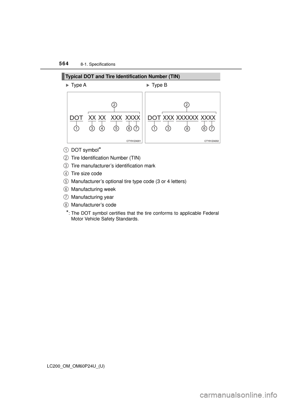
DOT symbol*
Tire Identification Number (TIN)
Tire manufacturer’s identification mark
Tire size code
Manufacturer’s optional tire type code (3 or 4 letters)
Manufacturing week
Manufacturing year
Manufacturer’s code
*: The DOT symbol certifies that the tire conforms to applicable Federal Motor Vehicle Safety Standards.
Typical DOT and Tire Identification Number (TIN)
Ty p e AType B
1
2
3
4
5
6
7
8