Page 630 of 732
6308-2. Steps to take in an emergency
HIGHLANDER_U (OM0E017U)
WARNING
■Speed limit when using the compact spare tire (vehicles with a
compact spare tire)
Do not drive at speeds in excess of 50 mph (80 km/h) when a compact
spare tire is installed on the vehicle.
The compact spare tire is not designed for driving at high speeds. Fail-
ure to observe this precaution may lead to an accident causing death or
serious injury.
■Replacing a flat tire for vehicles with power back door
In cases such as when replacing tires, make sure to turn off the power
back door main switch ( →P. 126). Failure to do so may cause the back
door to operate unintentionally if the power back door switch is acciden-
tally touched, resulting in hands and fingers being caught and injured.
■After using the tools and jack
Before driving, make sure all the tools and jack are securely in place in
their storage location to reduce the po ssibility of personal injury during a
collision or sudden braking.
Page 631 of 732

6318-2. Steps to take in an emergency
8
When trouble arises
HIGHLANDER_U (OM0E017U)
NOTICE
■Be careful when driving over bumps with the compact spare tire
installed on the vehicle.
The vehicle becomes lower when driving with the compact spare tire
compared to when driving with standard tires. Be careful when driving
over uneven road surfaces.
■Driving with tire chains and the compact spare tire
Do not fit tire chains to the compact spare tire.
Tire chains may damage the vehicle body and adversely affect driving
performance.
■When replacing the tires
When removing or fitting the wheels, tires or the tire pressure warning
valve and transmitter, contact your Toyota dealer as the tire pressure
warning valve and transmitter may be damaged if not handled correctly.
■To avoid damage to the tire pressure warning valves and transmit-
ters
When a tire is repaired with liquid sealants, the tire pressure warning
valve and transmitter may not operate properly. If a liquid sealant is
used, contact your Toyota dealer or other qualified service shop as soon
as possible. Make sure to replace the tire pressure warning valve and
transmitter when replacing the tire. ( →P. 533)
■When stowing the flat tire
●Ensure that there is no object caug ht between the tire and the vehicle
underbody.
●Securely tighten the spare tire clam p bolt to hold the spare wheel car-
rier by the hook.
●Stow the flat tire in the spare tire location. Failure to do so may cause
damage to the spare tire carrier. Proper storage redu ces the possibility
of injury in a collision or during sudden braking.
●Have the flat tire repaired and the spare tire replaced with it as soon as
possible.
Page 678 of 732

6789-1. Specifications
HIGHLANDER_U (OM0E017U)
*: Table 1 ⎯ Occupant loading and distribution for vehicle normal load for
various designated seating capacities
Section width
The linear distance between the exteriors of
the sidewalls of an inflated tire, excluding ele-
vations due to labeling, decoration, or protec-
tive bands
SidewallThat portion of a tire between the tread and
bead
Sidewall separationThe parting of the rubber compound from the
cord material in the sidewall
Snow tire
A tire that attains a traction index equal to or
greater than 110, compared to the ASTM E-
1136 Standard Reference Test Tire, when
using the snow traction test as described in
ASTM F-1805-00, Standard Test Method for
Single Wheel Driving Traction in a Straight
Line on Snow-and Ice-Covered Surfaces, and
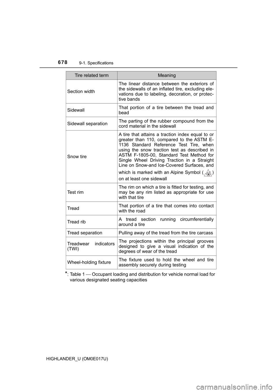
which is marked with an Alpine Symbol ( )
on at least one sidewall
Test rim
The rim on which a tire is fitted for testing, and
may be any rim listed as appropriate for use
with that tire
TreadThat portion of a tire that comes into contact
with the road
Tread ribA tread section running circumferentially
around a tire
Tread separationPulling away of the tread from the tire carcass
Treadwear indicators
(TWI)The projections within the principal grooves
designed to give a visual indication of the
degrees of wear of the tread
Wheel-holding fixtureThe fixture used to hold the wheel and tire
assembly securely during testing
Tire related termMeaning
Page 686 of 732
6869-2. Customization
HIGHLANDER_U (OM0E017U)■
Smart key system* (
→ P. 115, 123, 141)
*: If equipped
■
Wireless remote control ( →P. 108, 115, 123)
*: Vehicles without smart key system
■
Power back door* ( → P. 123)
*: If equipped
FunctionDefault settingCustomized set-
ting
Smart key systemOnOff——O
Number of consecutive
door lock operations2 timesAs many as
desired——O
123
FunctionDefault settingCustomized set- ting
Wireless remote controlOnOff——O
Unlocking operation
Driver’s door
unlocked in one step, all doors
unlocked in two
steps
All doors
unlocked in one step
O—O
Reservation lock*OnOffO—O
Alarm (panic mode)OnOff——O
123
FunctionDefault settingCustomized set-
ting
Power back door open-
ing angleOpening angle 5Opening angle 1 to 4O—O
123
Page 695 of 732
695
HIGHLANDER_U (OM0E017U)
10
For owners
●Déroulez la sangle diagonale
de telle sorte qu’elle passe bien
sur l’épaule, sans pour autant
être en contact avec le cou ou
glisser de l’épaule.
● Placez la sangle abdominale le
plus bas possible sur les
hanches.
● Réglez la position du dossier de sièg e. Asseyez-vous le dos droit et
calez-vous bien dans le siège.
● Ne vrillez pas la ceinture de sécurité.
Seat belt instructions for Canadian owners
(in French)
The following is a French explan ation of seat belt instructions
extracted from the seat be lt section in this manual.
See the seat belt secti on for more detailed seat belt instructions in
English.
Utilisation correcte des ceintures de sécurité
Page 696 of 732
696
HIGHLANDER_U (OM0E017U)
Si la sangle diagonale est proche du cou d’une personne, utilisez le
guide de confort de la ceinture de sécurité.
Sortez le guide de confort de sa
poche.
Glissez la ceinture dans la fente
du guide.
Le cordon élastique doit être der-
rière la ceinture de sécurité.
Attachez la ceinture de sécurité
et placez-la confortablement.
Guide de confort de ceinture de s écurité (siège central de la troi-
sième rangée)
1
2
3
Page 697 of 732
697
HIGHLANDER_U (OM0E017U)
10
For owners
■Ceintures de sécurité
Nettoyez avec un chiffon ou une éponge humectée d’eau savon-
neuse tiède. Vérifiez régulièrement que les ceintures ne sont pas
effilochées, entaillées ou exagérément usées.
Entretien et soin
AVERTISSEMENT
■ Détérioration et usure des ceintures de sécurité
Inspectez le système de ceintures de sécurité périodiquement. Contrôlez
l'absence de coupures, d'effilochages et de pièces desserrées. N’utilisez
pas une ceinture de sécurité défectueuse avant qu’elle ne soit remplacé\
e.
Une ceinture de sécurité défectueuse ne protège pas l’occupant de bless-
ures graves ou mortelles.
Page 700 of 732

700
HIGHLANDER_U (OM0E017U)
Votre véhicule est équipé de COUSSINS GONFLABLES INTELLI-
GENTS conçus selon les normes de sécurité américaines applicables
aux véhicules à moteur (FMVSS208). Le boîtier électronique (ECU)
des coussins gonflabl es régule le déploiem ent des coussins gon-
flables sur la base des informations qu’il reçoit des capteurs, etc., indi-
qués ci-dessus dans le schéma illu strant les composants du système.
Parmi ces informations figurent la gravité du choc et l’occupation du
véhicule par les passagers. Le d éploiement rapide des coussins gon-
flables est obtenu au moyen d’une réaction chimique dans les dispo-
sitifs pyrotechniques, qui pro duit un gaz inoffensif permettant
d’amortir le mouvem ent des occupants.
Coussin gonflable passager
avant
Coussins gonflables rideau
Capteurs d’impact latéral
(portes avant)
Témoins indicateurs “AIR
BAG ON” et “AIR BAG OFF”
Prétensionneurs de ceintures
de sécurité et limiteurs de
force
Coussins gonflables latéraux
Coussin gonflable d'assise
Témoin d’avertissement SRS
Coussin gonflable conducteur
Capteurs d’impact latéral
(arrière)
Contacteur de boucle de cein-
ture de sécurité du siège pas-
sager avant
Capteur de position du siège
conducteur
Contacteur de boucle de cein-
ture de sécurité conducteur
Coussin gonflable de genoux
du conducteur
Système de classification de
l’occupant du siège passager
avant (ECU et capteurs)
Capteurs d’impact avant
Boîtier électronique de cous-
sins gonflables
1
2
3
4
5
6
7
8
9
10
11
12
13
14
15
16
17