Page 159 of 505

2When driving
159
86_EE (OM18071E)
2-1. Driving proceduresDriving the vehicle ............ 160
Engine (ignition) switch (vehicles with a
smart entry &
start system) ................... 174
Engine (ignition) switch (vehicles without a
smart entry &
start system) ................... 183
Automatic transmission .... 186
Manual Transmission ....... 193
Turn signal lever ............... 197
Parking brake ................... 198
Horn .................................. 199
2-2. Instrument cluster Gauges and meters .......... 200
Indicators and warning lights ............................... 204
Multi-information display (monochrome display) .... 210
Multi-information display (color display) ................. 215 2-3. Operating the lights and
windshield wipers
Headlight switch................ 231
Fog light switch ................. 237
Windshield wipers and washer ............................ 238
2-4. Using other driving systems
Cruise control.................... 241
Driving assist systems ...... 246
Hill-start assist control....... 253
2-5. Driving information Cargo and luggage ........... 257
Winter driving tips ............. 259
Trailer towing .................... 263
Page 180 of 505

180
2-1. Driving procedures
86_EE (OM18071E)
■
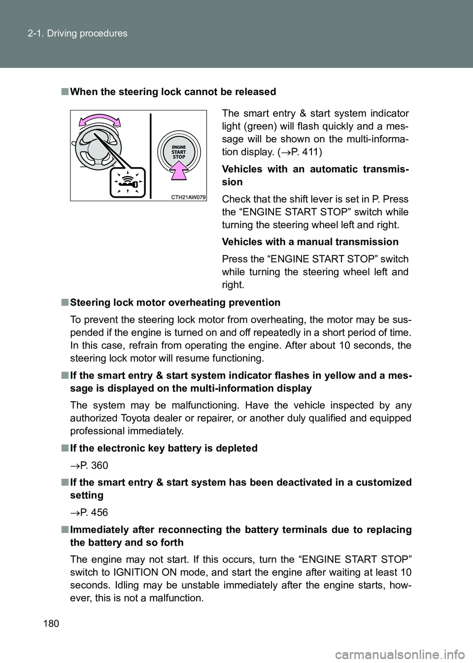
When the steering lock cannot be released
■ Steering lock motor overheating prevention
To prevent the steering lock motor from overheating, the motor may be sus-
pended if the engine is turned on and off repeatedly in a short period of time.
In this case, refrain from operating the engine. After about 10 seconds, the
steering lock motor will resume functioning.
■ If the smart entry & start system in dicator flashes in yellow and a mes-
sage is displayed on the multi-information display
The system may be malfunctioning. Have the vehicle inspected by any
authorized Toyota dealer or repairer, or another duly qualified and equipped
professional immediately.
■ If the electronic key battery is depleted
→ P. 360
■ If the smart entry & start system h as been deactivated in a customized
setting
→ P. 456
■ Immediately after reconnecting the battery terminals due to replacing
the battery and so forth
The engine may not start. If this occurs, turn the “ENGINE START STOP”
switch to IGNITION ON mode, and start the engine after waiting at least 10
seconds. Idling may be unstable immediately after the engine starts, how-
ever, this is not a malfunction. The smart entry & start system indicator
light (green) will flash quickly and a mes-
sage will be shown on the multi-informa-
tion display. (
→P. 411)
Vehicles with an automatic transmis-
sion
Check that the shift lever is set in P. Press
the “ENGINE START STOP” switch while
turning the steering wheel left and right.
Vehicles with a manual transmission
Press the “ENGINE START STOP” switch
while turning the steering wheel left and
right.
Page 187 of 505
187
2-1. Driving procedures
2
When driving
86_EE (OM18071E)
■
Shift position uses
*: Shifting to the D position allows the system to select a gear suitable for
the driving conditions. Setting the shift lever to the D position is recom-
mended for normal driving.
Shift
positionMulti-information display
FunctionMonochrome displayColor display
PParking the vehicle/start- ing the engine
RReversing
NNeutral
D
Normal D position driving*
(gears between “1” and “6” are automatically selected)
(paddle shift switches activated)(paddle shift switches activated)
Temporary manual mode
driving ( →P. 191)
MManual mode driving
(→ P. 189)
Page 189 of 505

189
2-1. Driving procedures
2
When driving
86_EE (OM18071E)
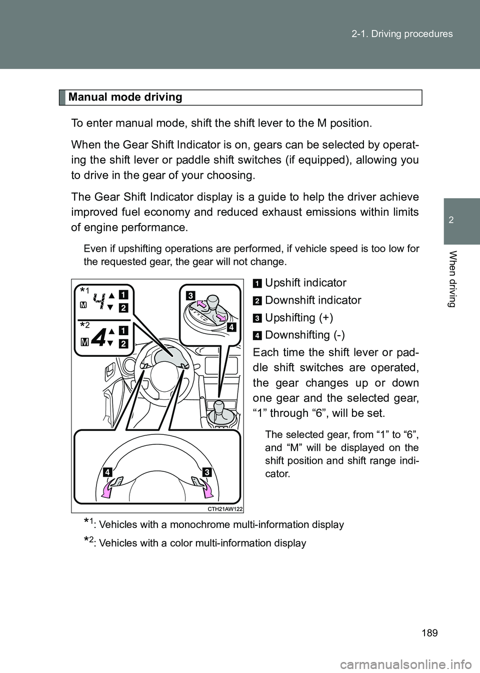
Manual mode driving
To enter manual mode, shift the shift lever to the M position.
When the Gear Shift Indicator is on, gears can be selected by operat-
ing the shift lever or paddle shift switches (if equipped), allowing you
to drive in the gear of your choosing.
The Gear Shift Indicator display is a guide to help the driver achieve
improved fuel economy and reduced exhaust emissions within limits
of engine performance.
Even if upshifting operations are performed, if vehicle speed is too low for
the requested gear, the gear will not change.
Upshift indicator
Downshift indicator
Upshifting (+)
Downshifting (-)
Each time the shift lever or pad-
dle shift switches are operated,
the gear changes up or down
one gear and the selected gear,
“1” through “6”, will be set.
The selected gear, from “1” to “6”,
and “M” will be displayed on the
shift position and shift range indi-
cator.
*1: Vehicles with a monochrome multi-information display
*2: Vehicles with a color multi-information display
*1
*2
Page 191 of 505

191
2-1. Driving procedures
2
When driving
86_EE (OM18071E)
■
Sport mode and snow mode automatic deactivation
In the following situations, the driving mode is automatically deactivated:
●When the engine is turned off after driving in sport mode or snow mode.
● When cruise control (if equipped) is ac tivated while driving in sport mode.
■ If the shift lever cannot be shifted from P
→ P. 453
■ Automatic gear selection when the vehicle is stopped
When the vehicle is idling at high rpm in order to warm up, and the vehicle is
on a slippery road, the transmission may automatically shift to 2
nd gear for
stopping and starting off.
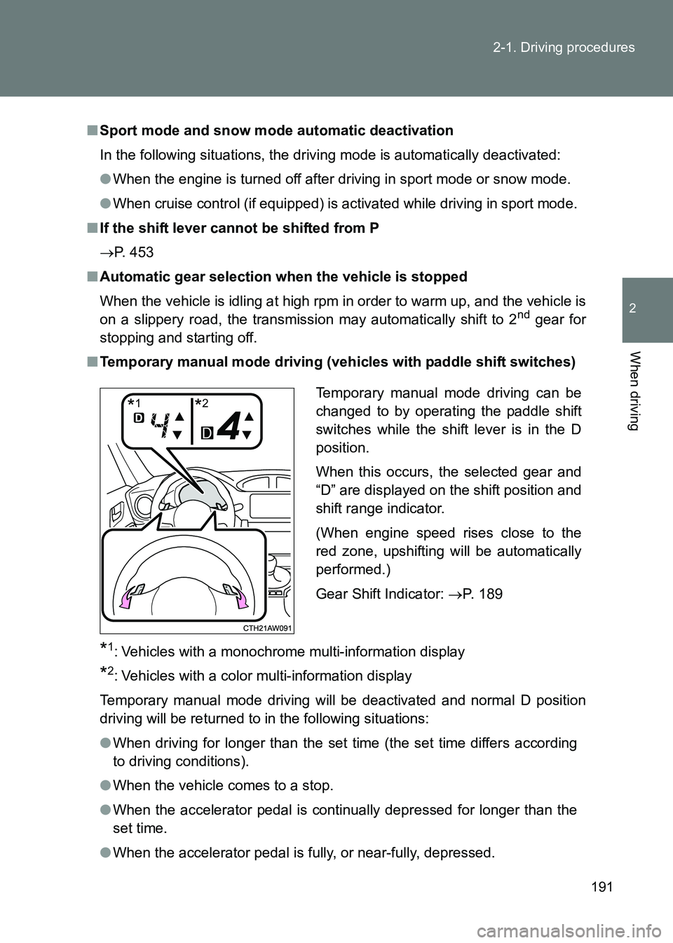
■ Temporary manual mode driving (vehicles with paddle shift switches)
*1: Vehicles with a monochrome multi-information display
*2: Vehicles with a color multi-information display
Temporary manual mode driving will be deactivated and normal D position
driving will be returned to in the following situations:
● When driving for longer than the set time (the set time differs according
to driving conditions).
● When the vehicle comes to a stop.
● When the accelerator pedal is continually depressed for longer than the
set time.
● When the accelerator pedal is fully, or near-fully, depressed. Temporary manual mode driving can be
changed to by operating the paddle shift
switches while the shift lever is in the D
position.
When this occurs, the selected gear and
“D” are displayed on the shift position and
shift range indicator.
(When engine speed rises close to the
red zone, upshifting will be automatically
performed.)
Gear Shift Indicator:
→P. 189
*1*2
Page 194 of 505
194
2-1. Driving procedures
86_EE (OM18071E)
Shift position indicator
The selected shift position will be
displayed on the multi-informa-
tion display.
The selected shift position will not
appear in the following situations:
• When the shift lever is in N.
• When the vehicle speed is 10km/h (6 mph) or less (except
when the shift lever is in R).
• When the clutch pedal is depressed.
*1: Vehicles with a monochrome multi-information display
*2: Vehicles with a color multi-information display
Gear Shift Indicator
The Gear Shift Indicator display is a guide to help the driver achieve
improved fuel economy and reduced exhaust emissions within limits
of engine performance. Upshift indicator
Downshift indicator
The Gear Shift Indicator cannot
be deactivated.
*1: Vehicles with a monochrome multi-information display
*2: Vehicles with a color multi-information display
*1*2
*1*2
Page 195 of 505

195
2-1. Driving procedures
2
When driving
86_EE (OM18071E)
■
Gear Shift Indicator display
●The Gear Shift Indicator may not be displayed when your foot is placed
on the clutch pedal.
● The Gear Shift Indicator may operate to prevent a possible engine stall at
a low engine speed.
WARNING
■Gear Shift Indicator
The indication of the gear shift indica tor is only as a guideline for driving
more fuel-efficiently. The indicator does not inform the driver about the safe
shift operation timing. The driver has t he responsibility for suitable shift oper-
ation depending on the traffic conditions or driving conditions (e.g., overtak-
ing or driving on an uphill slope).
This indicator supports the driver to dr ive more fuel-efficiently. The vehicle
system determines the shift operation timing depending on the driving condi-
tions, and informs the driver by the indicator on the combination meter. For
details, refer to Gear shift indicator.
Usually, the gear shift indicator is a guidel ine for driving more fuel-efficiently,
and it also may operate to prevent a possible stall at a low engine speed.
Page 200 of 505
200
86_EE (OM18071E)
2-2. Instrument cluster
Gauges and meters
The illustration below is for left-hand drive vehicles.
The switch positions may differ slightly for right-hand drive vehi-
cles.
With monochrome display
With color display
Type A Type B