2017 SUBARU LEGACY shift
[x] Cancel search: shiftPage 224 of 610

1) HomeLink®button 1
2) HomeLink®button 2
3) HomeLink®button 3
1. Press and hold the two outer buttons
(button 1 and button 3) until the indicator
light begins to flash (after approximately
20 seconds).
2. Release both buttons.
!In case a problem occurs
If you cannot activate a device using the
corresponding HomeLink
®button after
programming, contact HomeLink®at
www.homelink.com or call 1-800-355-
3515 for assistance.
& Auto-dimming mirror with
HomeLink
®(except U.S.-
spec. models - if equipped)
1) HomeLink®button 1
2) HomeLink®button 2
3) LED
4) HomeLink
®button 3
5) Sensor
6) Automatic dimming on button
7) Automatic dimming off button
The auto-dimming mirror has an anti-glare
feature which automatically reduces glare
coming from headlights of vehicles behind
you. It also contains a HomeLink
®wireless
control system.
By pressing the automatic dimming on/off
button, the automatic dimming function is
turned on or off. When the automatic dimming function is on, the LED indicator
will illuminate.
Even with the mirror in the automatic
dimming mode, the mirror surface turns
bright if the shift lever/select lever is
shifted into the
“R ”(reverse) position. This
is to ensure good rearward visibility during
reversing.
When cleaning the mirror, use a paper
towel or similar material dampened with
glass cleaner. Do not spray glass cleaner
directly on the mirror as that may cause
the liquid cleaner to enter the mirror
housing and damage the mirror.
! Photosensors
The mirror has a photosensor attached on
both the front and back sides. During
nighttime driving, these sensors detect
Instruments and controls/Mirrors
–CONTINUED –3-69
Page 276 of 610

!Display settings
Touch the
tab to set display.
Item Function
Day/Night
Mode The
“Auto ”, “Day ”or “Night ”key
can be selected on the pop-up
screen.
When the “Auto ”key is selected,
the screen changes to day or
night mode depending on the
position of the headlight switch.
Brightness Touch
“+” or“−” to adjust the
brightness.
NOTE
. When the screen is viewed through
polarized sunglasses, a rainbow pat-
tern may appear on the screen due to
optical characteristics of the screen. If
this is disruptive, please operate the screen without polarized sunglasses.
.
If the screen is set to “Day ”mode
with the headlight switch turned on,
this condition is memorized even with
the engine turned off.
! How to adjust the rear view
image
In the camera display, the brightness, tint,
color and black level of the screen can be
adjusted.
1. Depress the brake pedal fully and stop
the vehicle.
2. While the vehicle is stopped, set the
shift lever (MT models) or select lever
(CVT models) in the “R”position, and then
touch the display.
3. Touch the “Display Adjustment ”key.
4. Touch the items to adjust the rear
camera screen.
Camera display
WARNING
When adjusting camera display
screen, make sure to depress the
brake pedal fully to avoid the vehicle
from moving. Failure to do so may
lead to a serious accident.
NOTE
The camera display can be accessed
when the rear camera monitor is dis-
played.
Audio/Audio set
–CONTINUED –5-25
Page 286 of 610

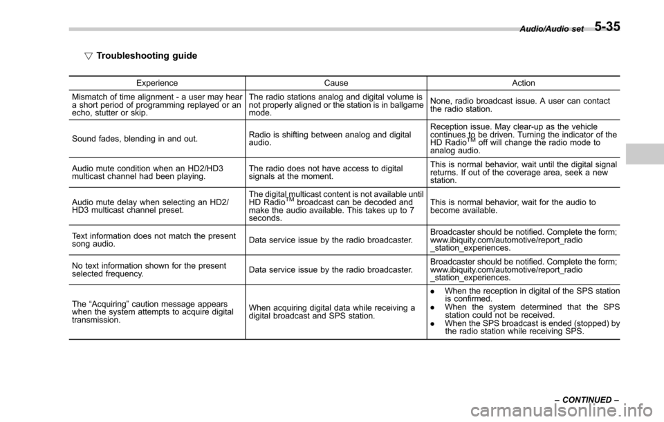
!Troubleshooting guide
Experience CauseAction
Mismatch of time alignment - a user may hear
a short period of programming replayed or an
echo, stutter or skip. The radio stations analog and digital volume is
not properly aligned or the station is in ballgame
mode.
None, radio broadcast issue. A user can contact
the radio station.
Sound fades, blending in and out. Radio is shifting between analog and digital
audio. Reception issue. May clear-up as the vehicle
continues to be driven. Turning the indicator of the
HD Radio
TMoff will change the radio mode to
analog audio.
Audio mute condition when an HD2/HD3
multicast channel had been playing. The radio does not have access to digital
signals at the moment. This is normal behavior, wait until the digital signal
returns. If out of the coverage area, seek a new
station.
Audio mute delay when selecting an HD2/
HD3 multicast channel preset. The digital multicast content is not available until
HD Radio
TMbroadcast can be decoded and
make the audio available. This takes up to 7
seconds. This is normal behavior, wait for the audio to
become available.
Text information does not match the present
song audio. Data service issue by the radio broadcaster. Broadcaster should be notified. Complete the form;
www.ibiquity.com/automotive/report_radio
_station_experiences.
No text information shown for the present
selected frequency. Data service issue by the radio broadcaster. Broadcaster should be notified. Complete the form;
www.ibiquity.com/automotive/report_radio
_station_experiences.
The “Acquiring ”caution message appears
when the system attempts to acquire digital
transmission. When acquiring digital data while receiving a
digital broadcast and SPS station. .
When the reception in digital of the SPS station
is confirmed.
. When the system determined that the SPS
station could not be received.
. When the SPS broadcast is ended (stopped) by
the radio station while receiving SPS. Audio/Audio set
–CONTINUED –
5-35
Page 353 of 610

Interior equipment/Cup holder
Cup holder
CAUTION
Take care to avoid spills. Beverages,
if hot, might burn you and/or your
passengers. Spilled beverages may
also damage upholstery, carpets or
audio equipment.
&Front passenger ’s cup holder
CAUTION
. Do not pick up a cup from the cup
holder or put a cup in the holder
while you are driving, as this may
distract you and lead to an
accident.
. Take care not to spill a beverage
on the shift lever/select lever or
any switch(es) in the adjacent
area. If the beverage is spilled, it
may cause a malfunction of the
shift lever/select lever and/or
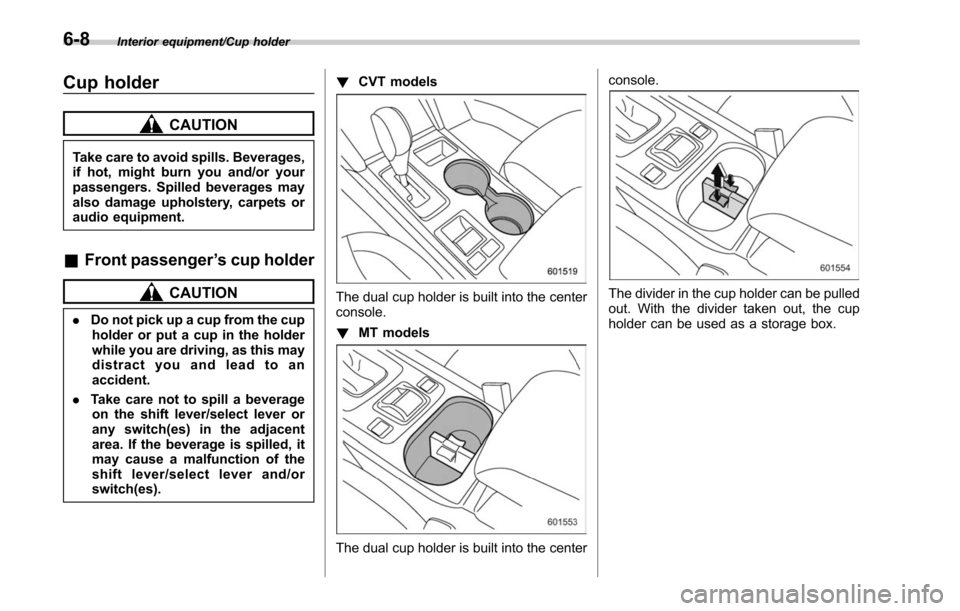
switch(es). !
CVT models
The dual cup holder is built into the center
console.
!MT models
The dual cup holder is built into the center console.
The divider in the cup holder can be pulled
out. With the divider taken out, the cup
holder can be used as a storage box.
6-8
Page 356 of 610

tight for the accessory power
outlet, this can result in a poor
contact or cause the plug to get
stuck. Only use plugs that fit
properly.
. Use of an electric appliance in the
accessory power outlet for a long
period of time while the engine is
not running can cause battery
discharge.
. Before driving your vehicle, make
sure that the plug and the cord
on your electrical appliance will
not interfere with your shifting
gears and operating the accel-
erator and brake pedals. If they
do, do not use the electrical
appliance while driving.
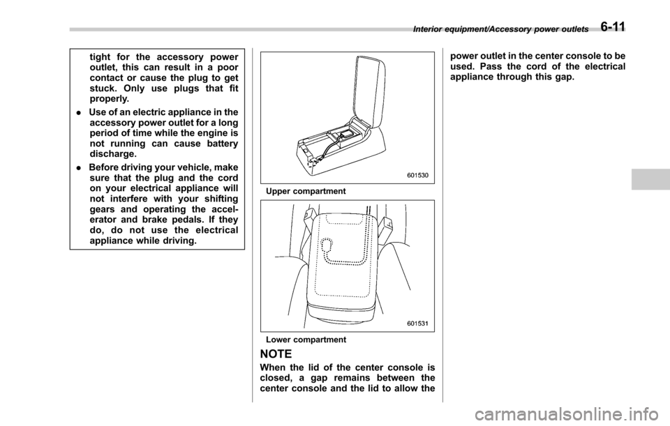
Upper compartment
Lower compartment
NOTE
When the lid of the center console is
closed, a gap remains between the
center console and the lid to allow the power outlet in the center console to be
used. Pass the cord of the electrical
appliance through this gap.
Interior equipment/Accessory power outlets6-11
Page 366 of 610

A rear view camera is attached to the
trunk lid (Legacy) or rear gate (Outback).
When the ignition switch is“ON ”and the
shift lever (MT models) or select lever
(CVT models) is set to “R”, the rear view
camera automatically displays the rear
view image behind the vehicle on the
audio/navigation monitor.
WARNING
. Since the rear view camera uses
a wide-angle lens, the image on
the monitor is different from the
actual view in terms of distance.
. Since the range of the image on
the monitor is limited, you should
always check the rear view and
the surrounding area with your
eyes and mirrors, and move
backward at a slow speed. Mov-
ing backward only by checking
the rear view image from the
camera could cause an accident.
. Do not disassemble or modify the
camera, switch or wiring. If
smoke comes out or you smell
a strange odor, stop using the
rear view camera immediately.
Contact your SUBARU dealer
for an inspection. Continued use
may result in accident, fire or electric shock.
CAUTION
.
If your vehicle is washed with a
high-pressure washer, do not
allow water to contact the camera
directly. Entry of water in the
camera lens may result in con-
densation, malfunction, fire or
electric shock.
. Since the camera is a precision
device, do not subject it to strong
impacts. Otherwise, malfunction,
fire or electric shock may occur.
. If mud or snow sticks to or is
frozen on the camera, you must
be very careful removing it.
Otherwise, damage done to the
camera may cause a fire or
electric shock. Pour water or
lukewarm water over the camera
to remove mud and ice, and wipe
it with a soft, dry cloth.
. Do not put a flame close to the
camera or wiring. Otherwise, da-
mage or fire may occur.
. When replacing the fuse, be sure
to use a fuse with the specified
rating. Use of a fuse with a
different rating may result in a malfunction.
. If the rear view camera is used for
a long time while the engine is
not operated, the battery may
become completely discharged.
NOTE
. Do not wipe the camera with alcohol,
benzine or paint thinner. Otherwise,
discoloration may occur. To remove
contamination, wipe the camera with a
cloth moistened with a diluted neutral
detergent and then wipe it with a soft,
dry cloth.
. When waxing the vehicle, be careful
not to apply the wax to the camera. If it
comes in contact with the camera,
moisten a clean cloth with a diluted
neutral detergent to remove the wax.
. The camera lens has hard coating to
help prevent scratches. However, when
washing the vehicle or cleaning the
camera lens, be careful not to scratch
the camera lens. Do not use a washing
brush directly on the camera lens. The
monitor screen may be adversely af-
fected.
. Strong light shined on the camera
lens may develop white light stripes
around the light source. This is not a
malfunction.
Interior equipment/Rear view camera
–CONTINUED –6-21
Page 367 of 610

Interior equipment/Rear view camera
.Under fluorescent lighting, the dis-
play may flicker. However, this is not a
malfunction.
. The image of the rear view camera
may be slightly different from the
actual color of the objects.
& How to use the rear view
camera
When performing the following procedure,
the rear view camera automatically dis-
plays the rear view image from the
vehicle.
1. Set the ignition switch to “ON”.
2. Set the shift lever or select lever to “R”.
When any of the following conditions
occur, the image before setting to “R”will
be displayed.
. Several seconds have passed after the
following operation (off delay function).
–Setting the shift lever to a position
other than “R”(MT models)
– Setting the select lever to a position
other than “P”or “R”(CVT models)
. The vehicle speed is more than 5 mph
(8 km/h).
. The select lever is set to “P”(CVT
models).
NOTE
. For models with the genuine
SUBARU navigation system or audio
system, the image of the rear view
camera has priority over other screen
displays. To operate other screens, set
the shift lever (MT models) or select
lever (CVT models) to a position other
than “R ”.
. The image of the rear view camera is
horizontally reversed as is the case
with the vehicle inside rear view mirror
or the side view mirror.
. It may be difficult to see the image of
the rear view camera in the following
cases. This is not a malfunction of the
camera.
–The vehicle is used for towing or
a trailer hitch is installed.
– The vehicle is in a dark place (at
night, in a tunnel, etc.).
– The vehicle is in an extremely hot
or cold place.
– An object (such as raindrops,
snow, dirt, etc.) that disturbs the
view of the rear view camera sticks
to the lens of the camera.
– Strong light shined directly on
the camera lens (occasionally, there
are vertical lines on the screen).& Viewing range on the screen
Range of view
Range of view
6-22
Page 369 of 610

Interior equipment/Rear view camera
&Help line
The help line (distance marker and vehicle
width line) is a guide to help you realize
the actual distance from the screen.
Help lines
1) Vehicle width line (oblique vertical line)
2) Approx. 10 feet (3 m) from the bumper
(green horizontal line)
3) Approx. 3 feet (1 m) from the bumper (yellow horizontal line)
4) Approx. 1.5 feet (0.5 m) from the bumper (red horizontal line)
5) Vehicle centerline
When the shift lever or select lever is set
to position “R”, the monitor screen dis-
plays the help lines together with the rear
view image.
CAUTION
. When moving backward, always
check the back with your eyes
without relying on the help lines.
. The actual position may be dif-
ferent from the indication of the
help lines.
. Differences may occur due to
number of passengers or loaded
cargo.
. When the vehicle is on a slope or
when the vehicle is inclined
against the road, the indication
is different from the actual posi-
tion.
. Be sure to observe the displayed
warning message “Check Sur-
roundings Before Backing Up ”.
NOTE
If you shift to the “R ” range shortly
after turning on the ignition switch, the
warning message “Check Surround-
ings Before Backing Up” may not be
displayed. Wait for several seconds or
more after turning on the ignition
switch before shifting to the “R ” range.
Then the warning message will be
displayed. !
Difference between screen and ac-
tual road
The distance markers show the distance
for a level road when the vehicle is not
loaded. It may be different from the actual
distance depending on the loading condi-
tions or road conditions.
!When there is an upward slope at
the back1) 3 feet (1 m)
The distance on the screen looks farther
than the actual distance.
6-24