2017 SUBARU FORESTER tires
[x] Cancel search: tiresPage 589 of 634

Specifications/Specifications
&Electrical system
Battery type Canada-spec. models 75D23L
Other models
55D23L
Alternator Non-turbo models
12V-150A
Turbo models 12V-130A
Spark plugs Non-turbo models
SILZKAR7B11 (NGK)
Turbo models ILKAR8H6 (NGK)
&
Tires
Vehicle model Non-turbo modelsTurbo models
Tire size P225/60R17 98HP225/55R18 97H P225/55R18 97H
Wheel size 1767J 1867J 1867J
Pressure Front 30 psi (210 kPa, 2.1 kgf/cm
2) 32 psi (220 kPa, 2.2 kgf/cm2) 33 psi (230 kPa, 2.3 kgf/cm2)
Rear 29 psi (200 kPa, 2.0 kgf/cm2) 30 psi (210 kPa, 2.1 kgf/cm2) 32 psi (220 kPa, 2.2 kgf/cm2)
Wheel nut tightening torque 89 lbf·ft (120 N·m, 12 kgf·m)*1
*1: This torque is equivalent to applying approximately 88 to 110 lbf (40 to 50 kgf) at the end of the wheel nut wrench. If you have tightened the wheel
nuts by yourself, have the tightening torque checked at the nearest automotive service facility as soon as possible. For the wheel nut tightening
procedure, refer to“Changing a flat tire ”F 9-5.
& Temporary spare tires
Temporary spare tire size T145/80D17185/65R17
Temporary spare tire inflation pressure
(recommended cold tire inflation pressure) 60 psi (420 kPa, 4.2 kgf/cm
2)
33 psi (230 kPa, 2.3 kgf/cm2)
12-10
Page 600 of 634
For U.S.A............................................................ 13-2
Tire information .................................................. 13-2
Tire labeling....................................................... 13-2
Recommended tire inflation pressure .................. 13-4
Glossary of tire terminology ............................... 13-5
Tire care –maintenance and safety
practices ........................................................ 13-10
Vehicle load limit –how to determine ................ 13-10 Determining compatibility of tire and vehicle
load capacities .............................................. 13-13
Adverse safety consequences of overloading on handling and stopping and on tires ........... 13-14
Steps for Determining Correct Load Limit ......... 13-14
Uniform tire quality grading standards.......... 13-15Treadwear....................................................... 13-15
Traction AA, A, B, C ......................................... 13-15
Temperature A, B, C ......................................... 13-15
Reporting safety defects (U.S.A.) ................... 13-16
Consumer information and Reporting safety defects
13
Page 602 of 634
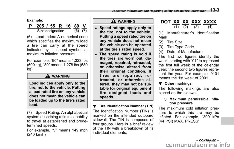
Example:
(6) Load Index: A numerical code
which specifies the maximum load
a tire can carry at the speed
indicated by its speed symbol, at
maximum inflation pressure.
For example,“90 ”means 1,323 lbs
(600 kg), “89 ”means 1,278 lbs (580
kg).
WARNING
Load indices apply only to the
tire, not to the vehicle. Putting
a load rated tire on any vehicle
does not mean the vehicle can
be loaded up to the tire ’s rated
load.
(7) Speed Rating: An alphabetical
system describing a tire ’s capability
to travel at established and prede-
termined speeds.
For example, “V ” means 149 mph
(240 km/h)
WARNING
.Speed ratings apply only to the tire, not to the vehicle.
Putting a speed rated tire on
any vehicle does not mean
the vehicle can be operated
at the tire ’s rated speed.
.The speed rating is void if
the tires are worn out, da-
maged, repaired, retreaded,
or otherwise altered from
their original condition. If
tires are repaired, re-
treaded, or otherwise al-
tered, they may not be sui-
table for original equipment
tire designed loads and
speeds.
! Tire Identification Number (TIN)
Tire Identification Number (TIN) is
marked on the intended outboard
sidewall. The TIN is composed of
four groups. Here is a brief review
of the TIN with a breakdown of its
individual elements.
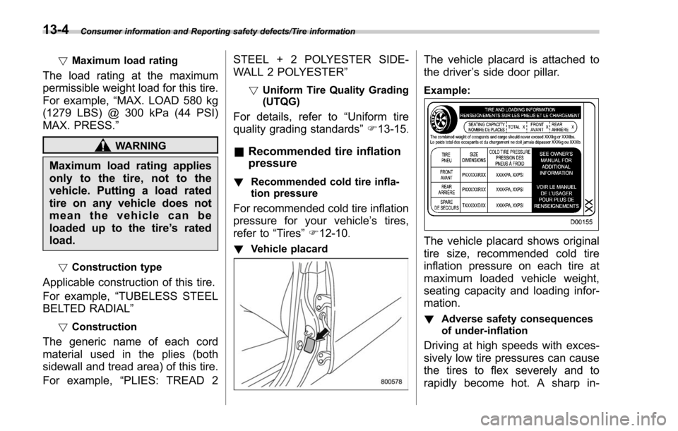
(1) Manufacturer ’s Identification
Mark
(2) Tire Size
(3) Tire Type Code
(4) Date of Manufacture
The first two figures identify the
week, starting with “01 ”to represent
the first full week of the calendar
year; the second two figures repre-
sent the year. For example, 0101
means the 1st week of 2001.
! Other markings
The following makings are also
placed on the sidewall.
!Maximum permissible infla-
tion pressure
The maximum cold inflation pres-
sure to which this tire may be
inflated. For example, “300 kPa
(44 PSI) MAX. PRESS ”
Consumer information and Reporting safety defects/Tire information
–CONTINUED –13-3
Page 603 of 634
Consumer information and Reporting safety defects/Tire information
!Maximum load rating
The load rating at the maximum
permissible weight load for this tire.
For example, “MAX. LOAD 580 kg
(1279 LBS) @ 300 kPa (44 PSI)
MAX. PRESS. ”
WARNING
Maximum load rating applies
only to the tire, not to the
vehicle. Putting a load rated
tire on any vehicle does not
mean the vehicle can be
loaded up to the tire ’s rated
load.
! Construction type
Applicable construction of this tire.
For example, “TUBELESS STEEL
BELTED RADIAL”
! Construction
The generic name of each cord
material used in the plies (both
sidewall and tread area) of this tire.
For example, “PLIES: TREAD 2 STEEL + 2 POLYESTER SIDE-
WALL 2 POLYESTER
”
!Uniform Tire Quality Grading
(UTQG)
For details, refer to “Uniform tire
quality grading standards ”F 13-15
.
& Recommended tire inflation
pressure
! Recommended cold tire infla-
tion pressure
For recommended cold tire inflation
pressure for your vehicle ’s tires,
refer to “Tires ”F 12-10
.
! Vehicle placard
The vehicle placard is attached to
the driver ’s side door pillar.
Example:
The vehicle placard shows original
tire size, recommended cold tire
inflation pressure on each tire at
maximum loaded vehicle weight,
seating capacity and loading infor-
mation.
! Adverse safety consequences
of under-inflation
Driving at high speeds with exces-
sively low tire pressures can cause
the tires to flex severely and to
rapidly become hot. A sharp in-
13-4
Page 604 of 634

crease in temperature could cause
tread separation, and failure of the
tire(s). Possible resulting loss of
vehicle control could lead to an
accident.
!Measuring and adjusting air
pressure to achieve proper in-
flation
Check and, if necessary, adjust the
pressure of each tire (including the
spare) at least once a month and
before any long journey. Check the
tire pressures when the tires are
cold. Use a pressure gauge to
adjust the tire pressures to the
specific values. Driving even a
short distance warms up the tires
and increases the tire pressures.
Also, the tire pressures are affected
by the outside temperature. It is
best to check tire pressure out-
doors before driving the vehicle.
When a tire becomes warm, the air
inside it expands, causing the tire
pressure to increase. Be careful not
to mistakenly release air from a
warm tire to reduce its pressure.
&Glossary of tire terminology
.Accessory weight
The combined weight (in excess of
those standard items which may be
replaced) of automatic transmis-
sion, power steering, power brakes,
power windows, power seats, radio,
and heater, to the extent that these
items are available as factory-in-
stalled equipment (whether in-
stalled or not).
.Bead
The part of the tire that is made of
steel wires, wrapped or reinforced
by ply cords and that is shaped to fit
the rim.
.Bead separation
A breakdown of the bond between
components in the bead.
.Bias ply tire
A pneumatic tire in which the ply
cords that extend to the beads are
laid at alternate angles substantially
less than 90 degrees to the center-
line of the tread.
.Carcass
The tire structure, except tread and sidewall rubber which, when in-
flated, bears the load.
.Chunking
The breaking away of pieces of the
tread or sidewall.
.Cold tire pressure
The pressure in a tire that has been
driven less than 1 mile or has been
standing for three hours or more.
.Cord
The strands forming the plies in the
tire.
.Cord separation
The parting of cords from adjacent
rubber compounds.
.Cracking
Any parting within the tread, side-
wall, or inner liner of the tire
extending to cord material.
.Curb weight
The weight of a motor vehicle with
standard equipment including the
maximum capacity of fuel, oil and
coolant, and if so equipped, air
conditioning and additional weight
optional engine.
Consumer information and Reporting safety defects/Tire information
–CONTINUED –13-5
Page 609 of 634

Consumer information and Reporting safety defects/Tire information
&Tire care –maintenance and
safety practices
.Check on a daily basis that the
tires are free from serious damage,
nails, and stones. At the same time,
check the tires for abnormal wear.
.Inspect the tire tread regularly
and replace the tires before their
tread wear indicators become visi-
ble. When a tire ’streadwear
indicator becomes visible, the tire
is worn beyond the acceptable limit
and must be replaced immediately.
With a tire in this condition, driving
at even low speeds in wet weather
can cause the vehicle to hydro-
plane. Possible resulting loss of
vehiclecontrolcanleadtoan
accident.
.To maximize the life of each tire
and ensure that the tires wear
uniformly, it is best to rotate the
tires every 7,500 miles (12,000 km).
For information about the tire rota-
tion order, refer to “Tire rotation ”
F 11-28
.Replace any damaged or
unevenly worn tires at the time of rotation. After tire rotation, adjust
the tire pressures and make sure
the wheel nuts are correctly tigh-
tened. For information about the
tightening torque and tightening
sequence for the wheel nuts, refer
to
“Flat tires” F9-5
.
& Vehicle load limit –how to
determine
The load capacity of your vehicle is
determined by weight, not by avail-
able cargo space. The load limit of
your vehicle is shown on the
vehicle placard attached to the
driver ’s side door pillar. Locate the
statement “The combined weight of
occupants and cargo should never
exceed XXX kg or XXX lbs ”on your
vehicle ’s placard.
Thevehicleplacardalsoshows
seating capacity of your vehicle.
The total load capacity includes the
total weight of driver and all pas-
sengers and their belongings, any
cargo, any optional equipment such
as a trailer hitch, roof rack or bike carrier, etc., and the tongue load of
a trailer. Therefore cargo capacity
can be calculated by the following
method.
Cargo capacity = Load limit
−(total
weight of occupants + total weight
of optional equipment + tongue
load of a trailer (if applicable))
For information about vehicle load-
ing, refer to “Loading your vehicle ”
F 8-12.
For information about towing capa-
city and weight limits, refer to
“Trailer towing ”F 8-19
.
13-10
Page 612 of 634
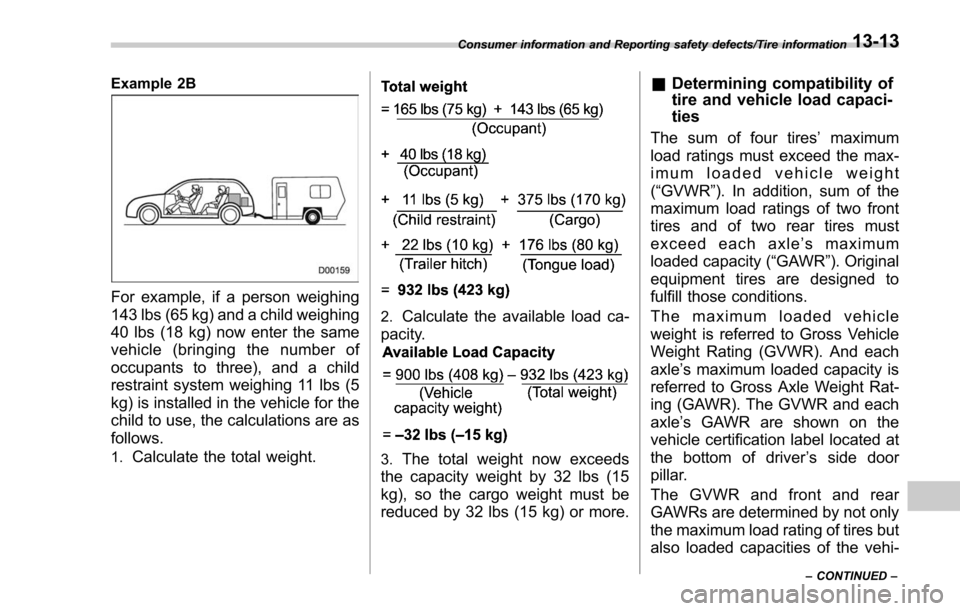
Example 2B
For example, if a person weighing
143 lbs (65 kg) and a child weighing
40 lbs (18 kg) now enter the same
vehicle (bringing the number of
occupants to three), and a child
restraint system weighing 11 lbs (5
kg) is installed in the vehicle for the
child to use, the calculations are as
follows.
1.Calculate the total weight.
2.Calculate the available load ca-
pacity.
3.The total weight now exceeds
the capacity weight by 32 lbs (15
kg), so the cargo weight must be
reduced by 32 lbs (15 kg) or more.
& Determining compatibility of
tire and vehicle load capaci-
ties
The sum of four tires ’maximum
load ratings must exceed the max-
imum loaded vehicle weight
( “GVWR ”). In addition, sum of the
maximum load ratings of two front
tires and of two rear tires must
exceed each axle ’smaximum
loaded capacity ( “GAWR ”). Original
equipment tires are designed to
fulfill those conditions.
The maximum loaded vehicle
weight is referred to Gross Vehicle
Weight Rating (GVWR). And each
axle ’s maximum loaded capacity is
referred to Gross Axle Weight Rat-
ing (GAWR). The GVWR and each
axle ’s GAWR are shown on the
vehicle certification label located at
the bottom of driver ’s side door
pillar.
The GVWR and front and rear
GAWRs are determined by not only
the maximum load rating of tires but
also loaded capacities of the vehi-
Consumer information and Reporting safety defects/Tire information
–CONTINUED –13-13
Page 613 of 634
Consumer information and Reporting safety defects/Tire information
cle’s suspension, axles and other
parts of the body.
Therefore, this means that the
vehicle cannot necessarily be
loaded up to the tire ’s maximum
load rating on the tire sidewall.
& Adverse safety conse-
quences of overloading on
handling and stopping and
on tires
Overloading could affect vehicle
handling, stopping distance, and
vehicle and tire performance in the
following ways. This could lead to
an accident and possibly result in
severe personal injury.
.Vehicle stability will deteriorate.
.Heavy and/or high-mounted
loads could increase the risk of
rollover.
.Stopping distance will increase.
.Brakes could overheat and fail.
.Suspension, bearings, axles and
other body parts could break or
experience accelerated wear that
will shorten vehicle life.
.Tires could fail.
.Tread separation could occur.
.Tire could separate from its rim.
& Steps for Determining Cor-
rect Load Limit
1.Locate the statement “The com-
bined weight of occupants and
cargo should never exceed XXX
kg or XXX lbs. ”on your vehicle ’s
placard.
2.Determine the combined weight
of the driver and passengers that
will be riding in your vehicle.
3.Subtract the combined weight of
the driver and passengers from
XXX kg or XXX lbs.
4.The resulting figure equals the
available amount of cargo and
luggage load capacity. For exam-
ple, if the “XXX ”amount equals
1400 lbs. and there will be five 150
lb passengers in your vehicle, the
amount of available cargo and
luggage load capacity is 650 lbs.
(1400 −750 (5 6150) = 650 lbs.)
5.Determine the combined weight of luggage and cargo being loaded
on the vehicle. That weight may not
safely exceed the available cargo
and luggage load capacity calcu-
lated in Step 4.
6.If your vehicle will be towing a
trailer, load from your trailer will be
transferred to your vehicle. Consult
this manual to determine how this
reduces the available cargo and
luggage load capacity of your ve-
hicle.
13-14