2017 SUBARU FORESTER Warning lights
[x] Cancel search: Warning lightsPage 441 of 634

Starting and operating/Electronic Brake Force Distribution (EBD) system
Electronic Brake Force Dis-
tribution (EBD) system
The EBD system maximizes the effective-
ness of the brakes by allowing the rear
brakes to supply a greater proportion of
the braking force. It functions by adjusting
the distribution of braking force to the rear
wheels in accordance with the vehicle’s
loading condition and speed.
The EBD system is an integral part of the
ABS and uses some of the ABS compo-
nents to perform its function of optimizing
the distribution of braking force. If any of
the ABS components used by the EBD
system malfunction, the EBD system also
stops working.
When the EBD system is operating, you
may hear a chattering noise or feel a slight
vibration in the brake pedal. This is normal
and does not indicate a malfunction.
& Steps to take if EBD system
malfunctions
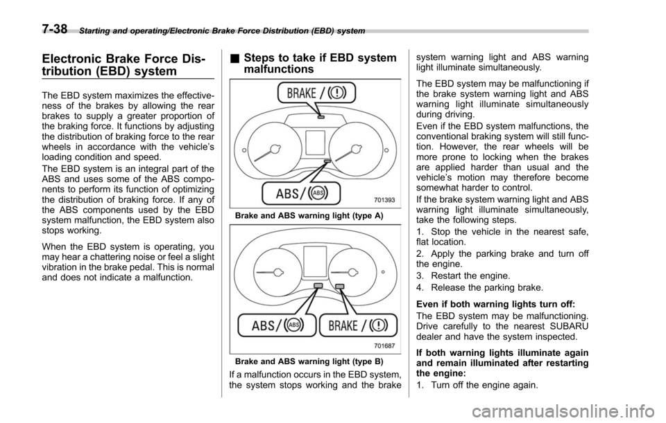
Brake and ABS warning light (type A)
Brake and ABS warning light (type B)
If a malfunction occurs in the EBD system,
the system stops working and the brake system warning light and ABS warning
light illuminate simultaneously.
The EBD system may be malfunctioning if
the brake system warning light and ABS
warning light illuminate simultaneously
during driving.
Even if the EBD system malfunctions, the
conventional braking system will still func-
tion. However, the rear wheels will be
more prone to locking when the brakes
are applied harder than usual and the
vehicle
’s motion may therefore become
somewhat harder to control.
If the brake system warning light and ABS
warning light illuminate simultaneously,
take the following steps.
1. Stop the vehicle in the nearest safe,
flat location.
2. Apply the parking brake and turn off
the engine.
3. Restart the engine.
4. Release the parking brake.
Even if both warning lights turn off:
The EBD system may be malfunctioning.
Drive carefully to the nearest SUBARU
dealer and have the system inspected.
If both warning lights illuminate again
and remain illuminated after restarting
the engine:
1. Turn off the engine again.
7-38
Page 465 of 634

Starting and operating/BSD/RCTA
signal lever is operated toward the side in
which this light turned on, the indicator
light flashes to warn the driver of dangers.
When reversing the vehicle, the indicator
light flashes when the system detects a
vehicle approaching from either side.! BSD/RCTA approach indicator
light dimming function
When the headlights are turned on, the
brightness of the BSD/RCTA approach
indicator light will be reduced.
NOTE
. When affected by direct sunlight,
you may have difficulty recognizing
the BSD/RCTA approach indicator light.
. When affected by the headlight
beams from the vehicles behind, you
may have difficulty recognizing the
BSD/RCTA approach indicator light.
. While the illumination brightness
control dial is in the fully upward
position, even if the headlights are
turned on, the brightness of the BSD/
RCTA approach indicator light will not
be reduced. For details about the
illumination brightness control dial,
refer to “Illumination brightness con-
trol” F3-101. !
BSD/RCTA approach warning buz-
zer (only when reversing)
A warning buzzer sounds along with
flashing of the BSD/RCTA approach in-
dicator light to warn the driver of dangers.
The setting of the warning buzzer volume
can be changed by operating the multi
information display of the combination
meter. For details, refer to “BSD/RCTA”
F 3-43.
! Safety tips regarding the BSD/RCTA
approach indicator light/warning
buzzer
. In the following cases, operation of the
BSD/RCTA approach indicator light and
the warning buzzer may be delayed or the
system may fail to issue these warnings.
–Whenavehiclemovestothe
neighboring lane from a lane next to
the neighboring lane
– When driving on a steep incline or
on repeated sharp uphill and downhill
grades
– When going beyond a pass
– When both your vehicle and a
vehicle driving on a neighboring lane
are driving on the far side of each lane.
– When several narrowly-spaced ve-
hicles are approaching in a row
– In low radius bends (tight bends or when making turns at an intersection)
–
When there is a difference in height
between your lane and the neighbor-
ing lane
– Immediately after the BSD/RCTA is
activated by pressing the BSD/RCTA
OFF switch
– Immediately after the shift lever/
select lever is shifted to the “R ”
position
– When extremely heavy cargo is
loaded in the trunk or cargo area
. During reversing, operation of the BSD/
RCTA approach indicator light and the
warning buzzer may be delayed or the
system may fail to issue these warnings
under the following conditions.
–When backing out of an angled
parking space
– When a large-sized vehicle is
parked next to your vehicle (That
vehicle prevents the propagation of
radar waves.)
– When reversing on sloped roads
– When reversing at a high speed
7-62
Page 495 of 634

Driving tips/Trailer hitch (dealer option)
receiver tube.
2. Insert the hitch pin into the hole
located on the hitch receiver tube so that
the pin passes through the ball mount.
3. Insert the safety pin through the
provided hole on the hitch pin securely.
4. Check the ball mount assembly by
pulling on it to make sure it does not come
off the hitch receiver.
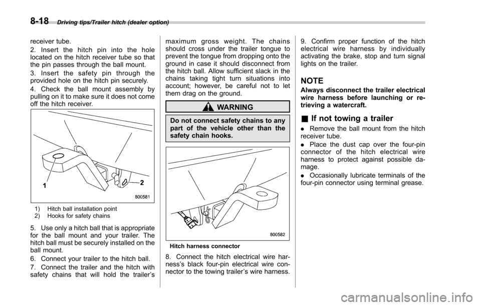
1) Hitch ball installation point
2) Hooks for safety chains
5. Use only a hitch ball that is appropriate
for the ball mount and your trailer. The
hitch ball must be securely installed on the
ball mount.
6. Connect your trailer to the hitch ball.
7. Connect the trailer and the hitch with
safety chains that will hold the trailer’s maximum gross weight. The chains
should cross under the trailer tongue to
prevent the tongue from dropping onto the
ground in case it should disconnect from
the hitch ball. Allow sufficient slack in the
chains taking tight turn situations into
account; however, be careful not to let
them drag on the ground.
WARNING
Do not connect safety chains to any
part of the vehicle other than the
safety chain hooks.
Hitch harness connector
8. Connect the hitch electrical wire har-
ness
’s black four-pin electrical wire con-
nector to the towing trailer ’s wire harness. 9. Confirm proper function of the hitch
electrical wire harness by individually
activating the brake, stop and turn signal
lights on the trailer.
NOTE
Always disconnect the trailer electrical
wire harness before launching or re-
trieving a watercraft.
&
If not towing a trailer
. Remove the ball mount from the hitch
receiver tube.
. Place the dust cap over the four-pin
connector of the hitch electrical wire
harness to protect against possible da-
mage.
. Occasionally lubricate terminals of the
four-pin connector using terminal grease.
8-18
Page 500 of 634

total, one to the right side and the other to
the left side trailer tongue. Pass the chains
crossing each other under the trailer
tongue to prevent the trailer from dropping
onto the ground in case the trailer tongue
should disconnect from the hitch ball.
Allow sufficient slack in the chains taking
tight turn situations into account; however,
be careful not to let them drag on the
ground.
!Side mirrors
After hitching a trailer to your vehicle,
check that the standard side mirrors
provide a good rearward field of view
without significant blind spots. If significant
blind spots occur with the vehicle’ s stan-
dard side mirrors, use towing mirrors that
conform with Federal, state/province and/
or other applicable regulations. !
Trailer lights
CAUTION
Direct splicing or other improper
connection of trailer lights may
damage your vehicle’ s electrical
system and cause a malfunction of
your vehicle ’s lighting system.
Connection of trailer lights to your vehi-
cle ’s electrical system requires modifica-
tions to the vehicle ’s lighting circuit to
increase its capacity and accommodate
wiring changes. To ensure the trailer lights
are connected properly, please consult
your SUBARU dealer. Check for proper
operation of the turn signals and the brake
lights each time you connect a trailer to
your vehicle.
! Tires
WARNING
Never tow a trailer when the tem-
porary spare tire is used. The tem-
porary spare tire is not designed to
sustain the towing load. Use of the
temporary spare tire when towing
can result in failure of the spare tire
and/or less stability of the vehicle.
Make sure that all the tires on your vehicle are properly inflated. Refer to
“Tires”F 12-
10.
Trailer tire condition, size, load rating and
proper inflation pressure should be in
accordance with the trailer manufacturer ’s
specifications. Also check federal, state,
province and/or other applicable regula-
tions.
In the event your vehicle gets a flat tire
when towing a trailer, ask a commercial
road service representative or profes-
sional to repair the flat tire.
If you carry a regular size spare tire in your
vehicle or trailer as a precaution against
getting a flat tire, be sure that the spare
tire is firmly secured.
& Trailer towing tips
CAUTION
. For models equipped with the
BSD (Blind Spot Detection) and
RCTA (Rear Cross Traffic Alert)
driving support systems, when
towing a trailer, press the BSD/
RCTA OFF switch to deactivate
the system. The system may not
operate properly due to the
blocked radar waves. For details
about the BSD/RCTA OFF switch,
Driving tips/Trailer towing
–CONTINUED –8-23
Page 570 of 634

Replacing bulbs
WARNING
Bulbs may become very hot while
illuminated. Before replacing bulbs,
turn off the lights and wait until the
bulbs cool down. Otherwise, there is
a risk of sustaining a burn injury.
CAUTION
Replace any bulb only with a new
bulb of the specified wattage. Using
a bulb of different wattage could
result in a fire. For the specified
wattage of each bulb, refer to“Bulb
chart” F12-16.
Do not touch the glass portion of the
light bulb with bare hands. When
holding the glass portion is una-
voidable, hold it using a clean dry
cloth to avoid getting moisture and
oils on the bulb. Also, if the bulb is
scratched or dropped, it may blow
out or crack.
NOTE
. For models with type A combination
meter, if SRH is malfunctioning, the SRH OFF indicator on the combination
meter blinks when the ignition switch is
in the
“ON ”position. It indicates that
SRH has been deactivated. Contact a
SUBARU dealer for an inspection.
. For models with type B combination
meter, if SRH is malfunctioning, a
message appears on the warning
screen when the ignition switch is in
the “ON ”position. It indicates that SRH
has been deactivated. Contact a
SUBARU dealer for an inspection.
& Headlights (models with LED
headlights)
The LED headlights may be malfunction-
ing if the headlights do not illuminate or if
they do not illuminate at the appropriate
brightness. In this case, have your vehicle
inspected at a SUBARU dealer as soon as
possible.
&Headlights (models with ha-
logen headlights)
CAUTION
Halogen headlight bulbs become
very hot while in use. If you touch
the bulb surface with bare hands or
greasy gloves, fingerprints or
grease on the bulb surface will develop into hot spots, causing the
bulb to break. If there are finger
prints or grease on the bulb surface,
wipe them away with a soft cloth
moistened with alcohol.
NOTE
.
If headlight aiming is required, con-
sult your SUBARU dealer for proper
adjustment of the headlight aim.
. It may be difficult to replace the
bulbs. Have the bulbs replaced by your
SUBARU dealer if necessary.
To replace the right side headlight bulb,
use a screwdriver to undo the clips on the
air intake duct, then remove the air intake
duct.
Maintenance and service/Replacing bulbs
–CONTINUED –11-39
Page 597 of 634

Specifications/Bulb chart
Wattage Bulb No.
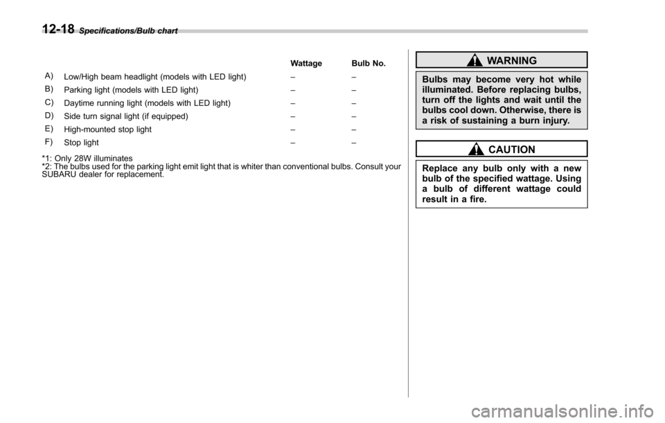
A) Low/High beam headlight (models with LED light) ––
B) Parking light (models with LED light) ––
C) Daytime running light (models with LED light) ––
D) Side turn signal light (if equipped) ––
E) High-mounted stop light ––
F) Stop light ––
*1: Only 28W illuminates
*2: The bulbs used for the parking light emit light that is whiter than conventional bulbs. Consult your
SUBARU dealer for replacement.WARNING
Bulbs may become very hot while
illuminated. Before replacing bulbs,
turn off the lights and wait until the
bulbs cool down. Otherwise, there is
a risk of sustaining a burn injury.
CAUTION
Replace any bulb only with a new
bulb of the specified wattage. Using
a bulb of different wattage could
result in a fire.
12-18
Page 621 of 634

14-6Index
Rear seat.............................................................. 1-12
Headlight Beam leveler ....................................................... 3-102
Bulb replacement .................................................. 11-39
Bulb wattage ....................................................... 12-16
Control switch ........................................................ 3-93
Flasher ................................................................. 3-98
Indicator light ......................................................... 3-33
OFF delay function ................................................. 3-94
Welcome lighting function ....................................... 3-94
HID headlights .......................................................... 11-39
High beam assist function ........................................... 3-95
Indicator light ......................................................... 3-32
High beam indicator light ............................................ 3-32
High/low beam change (dimmer) .................................. 3-95
Hill descent control ..................................................... 7-42
Indicator light ......................................................... 3-33
Hill start assist .................................................. 7-50, 11-21
OFF indicator light .................................................. 3-23
To activate/deactivate ............................................. 7-50
Warning light ......................................................... 3-23
HomeLink
®.............................................................. 3-109
Hook Cargo tie-down ...................................................... 6-16
Convenient ............................................................ 6-13
Shopping bag ........................................................ 6-13
Towing and tie-down ............................................... 9-13
Horn ........................................................................\
3-118
Hose and connections ............................................... 11-12 I
Ignition switch
............................................................. 3-4
Light ...................................................................... 3-6
Illumination brightness control .................................... 3-101
Immobilizer ................................................................. 2-3
Indicator light (security indicator light) ........................ 3-30
Indicator light BSD/RCTA OFF ............................................. 3-34, 7-64
BSD/RCTA warning ........................................ 3-33, 7-63
Coolant temperature low .......................................... 3-17
Cruise control ........................................................ 3-32
Cruise control set ................................................... 3-32
Front fog light ......................................................... 3-33
Headlight ............................................................... 3-33
High beam ............................................................. 3-32
High beam assist .................................................... 3-32
Hill descent control ................................................. 3-33
Hill start assist OFF ................................................ 3-23
Immobilizer ............................................................ 3-30
Security ................................................................. 3-30
Select lever/Gear position ........................................ 3-31
SI-DRIVE .............................................................. 3-31
Steering responsive fog lights OFF ... ........................ 3-33
Turn signal ............................................................ 3-32
Vehicle Dynamics Control OFF ................................. 3-25
Vehicle Dynamics Control operation .......................... 3-25
X-mode ................................................................. 3-33
Information display ...................................................... 3-34
Inside mirror ............................................................ 3-107
Interior lights ............................................................... 6-2
Page 623 of 634

14-8Index
Mirror defogger......................................................... 3-116
Mirrors .................................................................... 3-107
Moonroof .................................................................. 2-45
Multi function display .................................................. 3-44
Multi information display .............................................. 3-39
N
New vehicle break-in driving .......................................... 8-2
O
Odometer .................................................................. 3-10
Oil filter .................................................................... 11-11
Oil level
Engine ................................................................. 11-10
Front differential gear ............................................ 11-17
Manual transmission .............................................. 11-17
Rear differential gear ............................................. 11-17
Warning light ......................................................... 3-18
Oil pressure warning light ............................................ 3-18
On-road and off-road driving ...................................... 8, 8-6
Outside Mirror defogger ..................................................... 3-116
Mirrors ................................................................. 3-115
Temperature indicator ..................................... 3-34, 3-49
Overhead console ........................................................ 6-7
Overheating engine .................................................... 9-12
P
Parking Brake ................................................................... 7-47
Brake stroke ......................................................... 11-23 Tips ...................................................................... 7-48
Periodic inspections ..................................................... 8-4
Petrol fuel ................................................................... 7-3
PIN Code Access ....................................................... 2-19
Power Door locking switch .................................................. 2-8
Outlets ................................................................... 6-9
Outside mirrors .................................................... 3-115
Rear gate ...................................................... 2-39, 9-19
Seat ....................................................................... 1-5
Steering ................................................................ 7-34
Steering warning light .............................................. 3-23
Precautions against vehicle modification ................ 1-29, 1-72
Preparing to drive ........................................................ 7-8
Push-button Ignition switch ......................................................... 3-6
Starting and stopping engine .................................... 7-12
R
RCTA........................................................................\
7-59
Rear Combination lights ................................................ 11-42
Differential gear oil ........................................ 11-17, 12-7
Gate ............................................................. 2-38, 9-18
Turn signal light .................................................... 11-42
Rear seat .................................................................. 1-11
Folding down ......................................................... 1-13
Head restraint adjustment ........................................ 1-12
Heater ................................................................... 1-10
Reclining ............................................................... 1-15
Rear view camera ......................................................
6-17