2017 SUBARU FORESTER X mode
[x] Cancel search: X modePage 389 of 634
Interior equipment/Cup holders
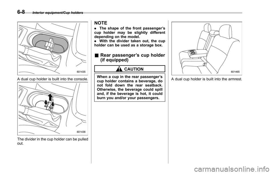
A dual cup holder is built into the console.
The divider in the cup holder can be pulled
out.
NOTE
.The shape of the front passenger ’s
cup holder may be slightly different
depending on the model.
. With the divider taken out, the cup
holder can be used as a storage box.
& Rear passenger ’s cup holder
(if equipped)
CAUTION
When a cup in the rear passenger ’s
cup holder contains a beverage, do
not fold down the rear seatback.
Otherwise, the beverage could spill
and, if the beverage is hot, it could
burn you and/or your passengers.A dual cup holder is built into the armrest.
6-8
Page 395 of 634
Interior equipment/Cargo area cover
Cargo area cover (if
equipped)
The cargo area cover is provided for
covering the cargo area and to protect its
contents from direct sunlight. This cover is
detachable to make room for additional
cargo.
&Using the cover
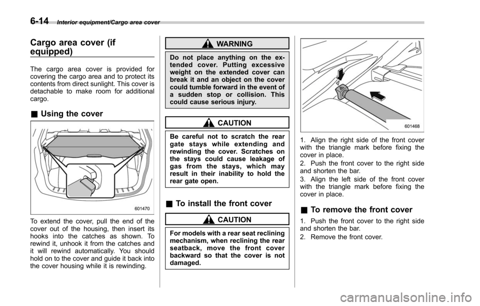
To extend the cover, pull the end of the
cover out of the housing, then insert its
hooks into the catches as shown. To
rewind it, unhook it from the catches and
it will rewind automatically. You should
hold on to the cover and guide it back into
the cover housing while it is rewinding.
WARNING
Do not place anything on the ex-
tended cover. Putting excessive
weight on the extended cover can
break it and an object on the cover
could tumble forward in the event of
a sudden stop or collision. This
could cause serious injury.
CAUTION
Be careful not to scratch the rear
gate stays while extending and
rewinding the cover. Scratches on
the stays could cause leakage of
gas from the stays, which may
result in their inability to hold the
rear gate open.
&To install the front cover
CAUTION
For models with a rear seat reclining
mechanism, when reclining the rear
seatback, move the front cover
backward so that the cover is not
damaged.
1. Align the right side of the front cover
with the triangle mark before fixing the
cover in place.
2. Push the front cover to the right side
and shorten the bar.
3. Align the left side of the front cover
with the triangle mark before fixing the
cover in place.
&To remove the front cover
1. Push the front cover to the right side
and shorten the bar.
2. Remove the front cover.
6-14
Page 398 of 634
Under-floor storage compart-
ment (if equipped)
NOTE
The shape of the storage compartment
may be different depending on the
model.
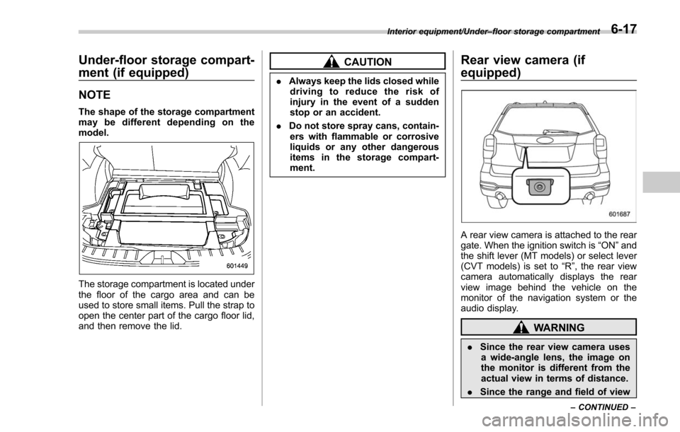
The storage compartment is located under
the floor of the cargo area and can be
used to store small items. Pull the strap to
open the center part of the cargo floor lid,
and then remove the lid.
CAUTION
.Always keep the lids closed while
driving to reduce the risk of
injury in the event of a sudden
stop or an accident.
. Do not store spray cans, contain-
ers with flammable or corrosive
liquids or any other dangerous
items in the storage compart-
ment.
Rear view camera (if
equipped)
A rear view camera is attached to the rear
gate. When the ignition switch is “ON”and
the shift lever (MT models) or select lever
(CVT models) is set to “R”, the rear view
camera automatically displays the rear
view image behind the vehicle on the
monitor of the navigation system or the
audio display.
WARNING
. Since the rear view camera uses
a wide-angle lens, the image on
the monitor is different from the
actual view in terms of distance.
. Since the range and field of view
Interior equipment/Under –floor storage compartment
–CONTINUED –6-17
Page 400 of 634
is displayed.
1. Set the ignition switch to“ON”.
2. Set the shift lever/select lever to “R”.
NOTE
. For models with the genuine
SUBARU navigation or audio system,
while the navigation system is acti-
vated, the image of the rear view
camera will not be displayed. However,
the image of the rear view camera has
priority over other screen displays.
. The image of the rear view camera
has priority over other screen displays.
. The image of the rear view camera is
horizontally reversed as is the case
with the vehicle rearview mirror or the
side view mirror.
. It may be difficult to see the image of
the rear view camera in the following
cases. This is not a malfunction of the
camera.
–The vehicle is used for towing or
a trailer hitch is installed.
– The vehicle is in a dark place (at
night, in a tunnel, etc.).
– The vehicle is in an extremely hot
or cold place.
– An object (such as raindrops,
snow, dirt, etc.) that disturbs the
view of the rear view camera sticks to the lens of the camera.
–
Strong light shined directly on
the camera lens (occasionally, there
are vertical lines on the screen).& Viewing range on the screen
CAUTION
The range that can be viewed with
the rear view camera is limited.
Always be sure to check with your
eyes when moving backward and
proceed slowly.
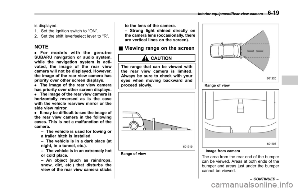
Range of view
Range of view
Image from camera
The area from the rear end of the bumper
can be viewed. Areas at both ends of the
bumper and areas just under the bumper
cannot be viewed.
Interior equipment/Rear view camera
–CONTINUED –6-19
Page 404 of 634

Fuel...................................................................... 7-3Fuel requirements ............................................... 7-3
Fuel filler lid and cap ........................................... 7-5
State emission testing (U.S. only) ...................... 7-7
Preparing to drive ............................................... 7-8
Starting and stopping the engine (models without push-button start system) .................. 7-9
Starting engine.................................................... 7-9
Stopping the engine ........................................... 7-11
Starting and stopping engine (models with
push-button start system) .............................. 7-12
Safety precautions............................................. 7-12
Operating range for push-button start system ............................................................. 7-12
Starting engine ................................................... 7-12
Stopping engine ................................................. 7-13
When access key does not operate properly ....... 7-14
Remote engine start system (dealer
option) .............................................................. 7-14
Models with “keyless access with push-button
start system ”................................................... 7-14
Models without “keyless access with push-button
start system ”................................................... 7-15
Entering the vehicle while it is running via remote start ................................................................. 7-19
Entering the vehicle following remote engine start shutdown ......................................................... 7-19
Pre-heating or pre-cooling the interior of the vehicle ............................................................. 7-19
Service mode (models without “keyless access
with push-button start system ”)........................ 7-19 Remote transmitter program (models without
“keyless access with push-button start
system ”).......................................................... 7-20
System maintenance .......................................... 7-20
Manual transmission ......................................... 7-22Shifting speeds.................................................. 7-23
Driving tips ........................................................ 7-24
Continuously variable transmission ................. 7-24Select lever....................................................... 7-25
Selection of manual mode (if equipped) .............. 7-27
Selection of “L ” (if equipped) ... .......................... 7-29
Shift lock function ............................................. 7-30
Driving tips ........................................................ 7-31
SI-DRIVE (if equipped) ....................................... 7-32Intelligent (I) mode............................................. 7-32
Sport (S) mode .................................................. 7-32
Sport Sharp (S#) mode. ...................................... 7-33
SI-DRIVE switches ............................................. 7-34
Power steering................................................... 7-34
Braking ............................................................... 7-35
Braking tips ....................................................... 7-35
Brake system .................................................... 7-36
Disc brake pad wear warning indicators ............. 7-36
ABS (Anti-lock Brake System).......................... 7-37ABS self-check.................................................. 7-37
ABS warning light .............................................. 7-37
Electronic Brake Force Distribution (EBD)
system ............................................................. 7-38
Steps to take if EBD system malfunctions .......... 7-38
Vehicle Dynamics Control system.................... 7-39Vehicle Dynamics Control system monitor .......... 7-41
Starting and operating
7
Page 405 of 634

Starting and operating
Vehicle Dynamics Control OFF switch................. 7-41
X-mode (if equipped).......................................... 7-42To activate/deactivate the X-mode ....................... 7-43
Hill descent control function ............................... 7-44
Tire pressure monitoring system (TPMS)
(U.S.-spec. models) ......................................... 7-46
Parking your vehicle .......................................... 7-47
Parking brake..................................................... 7-47
Parking tips ....................................................... 7-48
Hill start assist system ...................................... 7-49To activate/deactivate the Hill start assist
system ............................................................. 7-50
Hill start assist warning light/Hill start assist OFF indicator light ................................................... 7-52
Cruise control (if equipped). .............................. 7-53To set cruise control.......................................... 7-53
To temporarily cancel the cruise control ............. 7-55
To turn off the cruise control .............................. 7-55
To change the cruising speed ............................. 7-55
Cruise control indicator light .............................. 7-57
Cruise control set indicator light ......................... 7-57
BSD/RCTA (if equipped).................................... 7-58System features................................................. 7-58
System operation ............................................... 7-60
BSD/RCTA approach indicator light/warning buzzer ............................................................. 7-61
BSD/RCTA warning indicator .............................. 7-63
BSD/RCTA OFF switch ....................................... 7-64
Certification for the BSD/RCTA ........................... 7-65
Handling of radar sensors .................................. 7-65
Reverse Automatic Braking System (if
equipped) ........................................................ 7-66
Reverse Automatic Braking System overview .....7-67
Operating conditions ......................................... 7-67
Reverse Automatic Braking System operation ......................................................... 7-69
Canceling the Reverse Automatic Braking system operation ......................................................... 7-72
Reverse Automatic Braking system ON/OFF setting ............................................................. 7-72
RAB warning indicator ....................................... 7-73
Handling of the sonar sensors ........................... 7-73
Page 406 of 634
Fuel
CAUTION
Use of a fuel which is low in quality
or use of an inappropriate fuel
additive may cause damage to the
engine and/or fuel system.
&Fuel requirements
! Non-turbo models
The engine is designed to operate using
unleaded gasoline with an octane rating
of 87 AKI (90 RON) or higher .
! Turbo models
The engine is designed to operate at
maximum performance using unleaded
gasoline with an octane rating of 93 AKI
(98 RON) or higher . Unleaded gasoline
with an octane rating of 91 AKI (95 RON)
or higher may be used with no detriment to
engine durability or driveability. However,
you may notice a slight decrease in
maximum engine performance while using
91 AKI (95 RON) fuel.
Regular unleaded gasoline with an octane
rating of 87 AKI (90 RON) or higher may
also be used. Using regular unleaded gasoline will not be detrimental to engine
durability, nor will it affect your warranty
coverage. However, depending on your
driving habits and conditions, you may
notice a decrease in maximum engine
performance, fuel economy or slight en-
gine vibration or knocking. If you experi-
ence any of these conditions while using a
lower octane rated fuel, you may want to
return to using 91 AKI (95 RON) octane
rated fuel as soon as possible. Addition-
ally, if your vehicle knocks heavily or
persistently, or if you are driving with
heavy loads such as when towing a trailer,
the use of 91 AKI (95 RON) or higher
grade unleaded gasoline is required.
!
Fuel octane rating
Using a gasoline with a lower octane
rating can cause persistent and heavy
knocking, which can damage the engine.
Do not be concerned if your vehicle
sometimes knocks lightly when you drive
up a hill or when you accelerate. Contact
your SUBARU dealer if you use a fuel with
the specified octane rating and your
vehicle knocks heavily or persistently.
!RON
This octane rating is the Research Octane
Number. !
AKI
This octane rating is the average of the
Research Octane and Motor Octane
numbers and is commonly referred to as
the Anti Knock Index (AKI).
! Unleaded gasoline
The neck of the fuel filler pipe is designed
to accept only an unleaded gasoline filler
nozzle. Under no circumstances should
leaded gasoline be used because it will
damage the emission control system and
may impair driveability and fuel economy.
! Gasoline for California-certified
LEV
If your vehicle was certified to California ’s
low emission vehicle (LEV) standards as
indicated on the underhood tune-up label,
it is designed to optimize engine and
emission performance with gasoline that
meets the clean burning low-sulfur Cali-
fornia gasoline specifications. If you live in
any other state than California, your
vehicle will operate on gasoline meeting
Federal specifications. Gasoline sold out-
side California is permitted to have higher
sulfur levels, which may affect the perfor-
mance of your vehicle’ s catalytic converter
and may produce a sulfur exhaust odor or
smell. SUBARU recommends that you try
a different brand of unleaded gasoline
having lower sulfur to determine if the
Starting and operating/Fuel
–CONTINUED –7-3
Page 410 of 634

lead to fuel spillage and a fire.
. Immediately put fuel in the tank
whenever the low fuel warning
light illuminates. Engine misfires
as a result of an empty tank
could cause damage to the en-
gine. Continuing to operate your
vehicle at an extremely low fuel
level may result in a reduction of
engine performance.State emission testing (U.S.
only)
WARNING
Testing of an All-Wheel Drive model
must NEVER be performed on a
single two-wheel dynamometer. At-
tempting to do so will result in
uncontrolled vehicle movement and
may cause an accident or injuries to
persons nearby.
CAUTION
. At state inspection time, remem-
ber to tell your inspection or
service station in advance not to
place your SUBARU AWD vehicle
on a two-wheel dynamometer.
Otherwise, serious transmission
damage will result.
. Resultant vehicle damage due to
improper testing is not covered
under the SUBARU Limited War-
ranty and is the responsibility of
the state inspection program or
its contractors or licensees.
California and a number of federal states have Inspection/Maintenance programs to
inspect your vehicle
’s emission control
system. If your vehicle does not pass this
test, some states may deny renewal of
your vehicle’ s registration.
Your vehicle is equipped with a computer
that monitors the performance of the
engine’ s emission control system. Certi-
fied emission inspectors will inspect the
On-Board Diagnostic (OBDII) system as
part of the state emission inspection
process. The OBDII system is designed
to detect engine and transmission pro-
blems that might cause the vehicle emis-
sions to exceed allowable limits. OBDII
inspections apply to all 1996 model year
and newer passenger cars and trucks.
Over 30 states plus the District of Colum-
bia have implemented emission inspec-
tion of the OBDII system.
. The inspection of the OBDII system
consists of a visual operational check of
the “CHECK ENGINE ”warning light/mal-
function indicator light (MIL) and an
examination of the OBDII system with an
electronic scan tool.
. A vehicle
passes the OBDII system
inspection if proper operation of the
“ CHECK ENGINE ”warning light is ob-
served, there are no stored diagnostic
trouble codes, and the OBDII readiness
monitors are all complete.
Starting and operating/State emission testing (U.S. only)
–CONTINUED –7-7