Page 402 of 634
displayed.
!Difference between screen image
and actual road
The distance markers show the distance
for a level road when the vehicle is not
loaded. It may be different from the actual
distance depending on the loading condi-
tions or road conditions. !
When there is an upward slope at
the back
1) 3 feet (1 m)
The distance on the screen looks farther
than the actual distance. !
When there is a downward slope
at the back
1) 3 feet (1 m)
The distance on the screen looks nearer
than the actual distance.
NOTE
When cargo is loaded, the rear view
distance on the screen looks farther
thantheactualdistanceasinan
upward slope.
Interior equipment/Rear view camera
–CONTINUED –6-21
Page 403 of 634
Interior equipment/Rear view camera
!Feature of distance marker
1) 3 feet (1 m) line
2) 10 feet (3 m) line
The distance marker shows the distance
on the road. If there is a car or other object
close behind, distance cannot be correctly
displayed.
6-22
Page 436 of 634

power desired by those who want to make
the driving experience their own personal
adventure.
&Sport Sharp (S#) mode
! For maximum performance driving
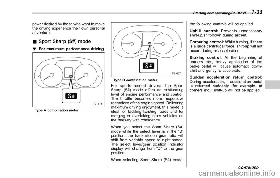
Type A combination meter
Type B combination meter
For sports-minded drivers, the Sport
Sharp (S#) mode offers an exhilarating
level of engine performance and control.
The throttle becomes more responsive
regardless of the engine speed. Delivering
maximum driving enjoyment, this mode is
ideal for tackling twisting roads and for
merging or overtaking other vehicles on
the freeway with confidence.
When you select the Sport Sharp (S#)
mode while the select lever is in the “D”
position, the transmission gear ratio will
shift from variable speed to eight-speed.
The select lever/gear position indicator
display will change from “D”to the gear
position.
When selecting Sport Sharp (S#) mode, the following controls will be applied.
Uphill control:
Prevents unnecessary
shift-up/shift-down during ascent.
Cornering control: While turning, if there
is a large centrifugal force, shift-up will not
occur: during re-acceleration.
Braking control: At the beginning of
corners etc., heavy application of the
brake pedal will cause automatic down-
shift and gently re-accelerate.
Sudden acceleration return control:
During acceleration, if acceleration pedal
is returned suddenly (for example, at
corners etc.), shift-up will not be applied.
Starting and operating/SI– DRIVE
– CONTINUED –7-33
Page 460 of 634

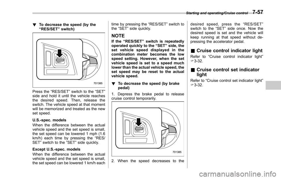
!To decrease the speed (by the
“RES/SET ”switch)
Press the “RES/SET”switch to the “SET”
side and hold it until the vehicle reaches
the desired speed. Then, release the
switch. The vehicle speed at that moment
will be memorized and treated as the new
set speed.
U.S.-spec. models
When the difference between the actual
vehicle speed and the set speed is small,
the set speed can be lowered 1 mph (1.6
km/h) each time by pressing the “RES/
SET ”switch to the “SET”side quickly.
Except U.S.-spec. models
When the difference between the actual
vehicle speed and the set speed is small,
the set speed can be lowered 1 km/h each time by pressing the
“RES/SET”switch to
the “SET ”side quickly.
NOTE
If the “RES/SET ”switch is repeatedly
operated quickly to the “SET ”side, the
set vehicle speed displayed in the
combination meter becomes the low
speed setting. However, when the set
vehicle speed is set to a speed much
lower than the actual vehicle speed, the
set speed may be reset to the actual
vehicle speed.
! To decrease the speed (by brake
pedal)
1. Depress the brake pedal to release
cruise control temporarily.
2. When the speed decreases to the desired speed, press the
“RES/SET ”
switch to the “SET”side once. Now the
desired speed is set and the vehicle will
keep running at that speed without de-
pressing the accelerator pedal.
& Cruise control indicator light
Refer to “Cruise control indicator light ”
F 3-32.
& Cruise control set indicator
light
Refer to “Cruise control set indicator light ”
F 3-32.
Starting and operating/Cruise control7-57
Page 465 of 634

Starting and operating/BSD/RCTA
signal lever is operated toward the side in
which this light turned on, the indicator
light flashes to warn the driver of dangers.
When reversing the vehicle, the indicator
light flashes when the system detects a
vehicle approaching from either side.! BSD/RCTA approach indicator
light dimming function
When the headlights are turned on, the
brightness of the BSD/RCTA approach
indicator light will be reduced.
NOTE
. When affected by direct sunlight,
you may have difficulty recognizing
the BSD/RCTA approach indicator light.
. When affected by the headlight
beams from the vehicles behind, you
may have difficulty recognizing the
BSD/RCTA approach indicator light.
. While the illumination brightness
control dial is in the fully upward
position, even if the headlights are
turned on, the brightness of the BSD/
RCTA approach indicator light will not
be reduced. For details about the
illumination brightness control dial,
refer to “Illumination brightness con-
trol” F3-101. !
BSD/RCTA approach warning buz-
zer (only when reversing)
A warning buzzer sounds along with
flashing of the BSD/RCTA approach in-
dicator light to warn the driver of dangers.
The setting of the warning buzzer volume
can be changed by operating the multi
information display of the combination
meter. For details, refer to “BSD/RCTA”
F 3-43.
! Safety tips regarding the BSD/RCTA
approach indicator light/warning
buzzer
. In the following cases, operation of the
BSD/RCTA approach indicator light and
the warning buzzer may be delayed or the
system may fail to issue these warnings.
–Whenavehiclemovestothe
neighboring lane from a lane next to
the neighboring lane
– When driving on a steep incline or
on repeated sharp uphill and downhill
grades
– When going beyond a pass
– When both your vehicle and a
vehicle driving on a neighboring lane
are driving on the far side of each lane.
– When several narrowly-spaced ve-
hicles are approaching in a row
– In low radius bends (tight bends or when making turns at an intersection)
–
When there is a difference in height
between your lane and the neighbor-
ing lane
– Immediately after the BSD/RCTA is
activated by pressing the BSD/RCTA
OFF switch
– Immediately after the shift lever/
select lever is shifted to the “R ”
position
– When extremely heavy cargo is
loaded in the trunk or cargo area
. During reversing, operation of the BSD/
RCTA approach indicator light and the
warning buzzer may be delayed or the
system may fail to issue these warnings
under the following conditions.
–When backing out of an angled
parking space
– When a large-sized vehicle is
parked next to your vehicle (That
vehicle prevents the propagation of
radar waves.)
– When reversing on sloped roads
– When reversing at a high speed
7-62
Page 467 of 634
Starting and operating/BSD/RCTA
!System malfunction indicator
System malfunction indicator (type A)
System malfunction indicator (type B)
1) At first, this message will appear
2) Then this message will appear
This indicator appears when a malfunction occurs in the system. Contact a SUBARU
dealer and have the system inspected.
&
BSD/RCTA OFF switch
BSD/RCTA OFF switch
BSD/RCTA OFF indicator (type A)
BSD/RCTA OFF indicator (type B)
If the BSD/RCTA OFF switch is pressed,
the BSD/RCTA OFF indicator appears on
the multi information display of the combi-
nation meter, and the BSD/RCTA is
deactivated.
Press the switch again to activate the
BSD/RCTA. The BSD/RCTA OFF indica-
tor will disappear.
NOTE
. In the following cases, the system
may not operate properly due to
blocked radar waves. Press the BSD/
RCTA OFF switch to deactivate the
system.
–When towing a trailer
– When a bicycle carrier or other
item is fitted to the rear of the
7-64
Page 472 of 634

Parts attached to the rear bumper
near the sonar sensor– Commercial electronic parts (fog
light, fender pole, radio antenna) or
commercial attachment parts (trai-
ler hitch, bicycle carrier, bumper
guard) are attached
– Parts that emit high frequency
sound, such as a horn or speaker,
are attached
Vehicle conditions – The vehicle is significantly in-
clined
– The ground clearance is signifi-
cantly reduced due to the vehicle ’s
loading condition, etc.
– When the sonar sensor is mis-
aligned due to a collision or an
accident
Surrounding environment – A cloth banner, flag, hanging
branch or railroad crossing bars
are present in the reversing direc-
tion
– When reversing on a gravel or
grassy area
– When reversing in an area where
objects or walls are adjacent to the
vehicle such as narrow tunnels,
narrow bridges, narrow roads or narrow garages
–
Wheel tracks or a hole is present
in the ground of the reversing
direction
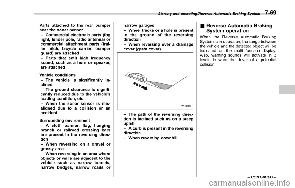
– When reversing over a drainage
cover (grate cover)
– The path of the reversing direc-
tion is inclined such as on a steep
uphill
– A curb is present in the reversing
direction
– When reversing downhill
& Reverse Automatic Braking
System operation
When the Reverse Automatic Braking
System is in operation, the range between
the vehicle and the detected object will be
indicated on the multi function display.
Also, warning sounds will activate in 3
levels to warn the driver of a potential
collision.
Starting and operating/Reverse Automatic Braking System
–CONTINUED –7-69
Page 473 of 634
Starting and operating/Reverse Automatic Braking System
Guideline of detecting rangeAlarm pattern Range of detected object* Distance indicator Warning sounds
Long proximity warn-
ing (Obstacle detect
warning) 35 inches (90 cm) or more Green
No warning sound
Medium proximity
warning (First braking
and warning - yellow) 28 to 35 inches (70 to 90
cm)
Yellow + Green Short beeps
Short proximity warn-
ing (First braking and
warning - orange) 20 to 28 inches (50 to 70
cm)
Orange + Yellow +
Green
Rapid short beeps
Closest proximity
warning (Second
braking and warning) 20 inches (50 cm) or less
Red + Orange +
Yellow + GreenContinuous beep
*: Range of detection may vary depending on the environmental condition.
Range of detected object
1) Green: 35 inches (90 cm) or more
1) Obstacle detect warning:
When an object is detected in the rever-
sing direction, the range of detected object
will be indicated on the multi function
display.
7-70