2017 SUBARU FORESTER horn
[x] Cancel search: hornPage 269 of 634
Instruments and controls/Tilt/telescopic steering wheel
Tilt/telescopic steering wheel
WARNING
.Do not adjust the steering wheel
tilt/telescopic position while driv-
ing. This may cause loss of
vehicle control and result in
personal injury.
. If the lever cannot be raised to
the fixed position, adjust the
steering wheel again. It is dan-
gerous to drive without locking
the steering wheel. This may
cause loss of vehicle control
and result in personal injury.
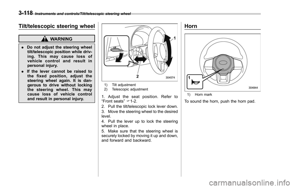
1) Tilt adjustment
2) Telescopic adjustment
1. Adjust the seat position. Refer to
“Front seats ”F 1-2.
2. Pull the tilt/telescopic lock lever down.
3. Move the steering wheel to the desired
level.
4. Pull the lever up to lock the steering
wheel in place.
5. Make sure that the steering wheel is
securely locked by moving it up and down,
and forward and backward.
Horn
1) Horn mark
To sound the horn, push the horn pad.
3-118
Page 419 of 634
Starting and operating/Remote engine start system (dealer option)
operating range of the system and the
start request is received, the following
phenomena will occur.
.The fob flashes and beeps once.
. The horn sounds once.
. The side marker lights, tail lights, and
parking lights flash once.
If the fob is not within range (the user is
too far away from the vehicle), the fob will
indicate two long flashes without beeping.
The system will check certain safety
preconditions before starting, and if all
conditions are met, the engine will start
within 5 seconds. After the engine starts,
the following phenomena will occur.
. The fob flashes and beeps twice.
. The horn sounds once.
. The side marker lights, tail lights, and
parking lights flash once.
While the engine is idling via the remote
engine start system, the following phe-
nomena will occur.
. The side marker lights, tail lights, and
parking lights remain illuminated.
. The fob button flashes once every 3
seconds.
. The power windows are disabled.
If the engine turns over but does not start
(or starts and stalls) the remote engine start system will power off and then
attempt to start the engine 3 additional
times. The system will not attempt to
restart the engine if it determines a vehicle
malfunction is preventing starting. If the
engine does not start after 3 additional
attempts, the remote engine start request
will be aborted.
!
Stopping the engine
Press and hold the fob button for at least 2
seconds to stop the engine. The fob will
flash and beep three times, indicating the
engine has stopped. If the stop request is
not received (for example, if the user is too
far away from the vehicle), the fob will
continue to flash once every 3 seconds.
The system will automatically stop the
engine after 15 minutes.
! Remote start safety features
For safety and security reasons, the
remote engine start system will prevent
starting (or stop the engine if running) and
sound the horn twice if any of the following
conditions is detected. In addition, the fob
will flash and beep 3 times.
. The brake pedal is depressed
. A key is in the ignition switch
. The engine hood is open
. The remote start system “Service
mode ”is engaged
. The engine idle speed exceeds 3,500 RPM
.
The security alarm is triggered
. The select lever is not in the “P ”
position
If the system detects any door (including
the rear gate) open during operation, it will
prevent starting or stop the engine, and
sound the horn and flash side marker
lights, tail lights, and parking lights 6
times.
In addition to the items above, if the
vehicle’ s engine management system
determines there is a safety risk due to a
vehicle-related problem, the vehicle will
power down and the horn will sound 3
times.
NOTE
. If the alarm system is armed at the
time of remote engine starter activation
(the security indicator light on the
combination meter is flashing), the
alarm system will remain armed
throughout the remote start run cycle.
. If the alarm system is disarmed at
the time of remote engine starter
activation (the security indicator light
on the combination meter is not flash-
ing), the alarm system will remain
disarmed throughout the remote start
run cycle.
7-16
Page 422 of 634
&Entering the vehicle while it
is running via remote start
1. Unlock the vehicle doors using the
keyless access function (if equipped) or
remote keyless entry system. If the vehi-
cle’s doors are unlocked manually using
the key, the vehicle’ s alarm system will
trigger (if the alarm system is armed prior
to activating the remote engine start
system) and the engine will turn off.
Perform either of the following procedures
to disarm the alarm system. Refer to
“Alarm system ”F 2-25.
. Insert the key into the ignition switch
and turn it to the “ON”position (models
without “keyless access with push-
button start system ”)
. Turn the push-button ignition switch
to the “ACC”or “ON ”position (models
with “keyless access with push-button
start system ”)
. Press any button on the access key/
remote keyless entry transmitter.
2. Enter the vehicle.
3. The engine will shut down when any
door or rear gate is opened.
4. For models without “keyless access
with push-button start system ”, insert the
key into the ignition switch and turn to the
“START ”position to restart the engine. For
models with “keyless access with push- button start system
”, press the push-
button ignition switch while depressing
the brake pedal to restart the engine.
& Entering the vehicle follow-
ing remote engine start shut-
down
An alarm trigger may occur if the vehicle is
opened by the remote keyless entry
transmitter within a few seconds immedi-
ately following remote engine start shut-
down.
&Pre-heating or pre-cooling
the interior of the vehicle
Before exiting the vehicle, set the tem-
perature controls to the desired setting
and operation. After the system starts the
engine, the heater or air conditioning will
activate and heat or cool the interior to
your setting.
&Service mode (models with-
out “keyless access with
push-button start system ”)
In service mode, the remote engine start
function is temporarily disabled to prevent
the system from unexpectedly starting the
engine while being serviced. To engage or disengage service mode:
1. Enter the vehicle and close all vehicle
doors and the rear gate.
2. Verify that the select lever is in the
“P ”
position (CVT models)
3. Depress and hold the brake pedal
4. Turn the ignition switch to the “ON”
position
5. Press and release the remote engine
start transmitter “
”button three times.
The system will honk the vehicle ’s horn
each time the button is pressed.
6. The system will pause for 1 second
then honk the vehicle’ s horn three times to
indicate that the service mode has been
engaged or honk one time to indicate that
the service mode has been disengaged.
NOTE
When taking your vehicle in for service,
it is recommended that you inform the
service personnel that your vehicle is
equipped with a remote engine start
system.
Starting and operating/Remote engine start system (dealer option)
–CONTINUED –7-19
Page 423 of 634
Starting and operating/Remote engine start system (dealer option)
&Remote transmitter program
(models without “keyless ac-
cess with push-button start
system ”)
New transmitters can be programmed to
the remote engine start system in the
event that a transmitter is lost, stolen,
damaged or additional transmitters are
desired (the system will accept up to eight
transmitters). New remote engine start
transmitters can be programmed accord-
ing to the following procedure.
1. Open the driver ’s door (the driver ’s
door must remain opened throughout the
entire process).
2. Depress and hold the brake pedal.
3. Turn the ignition switch to “ON”then
“LOCK” , back to “ON”then “LOCK ”, back
to “ON ”then “LOCK”, then back to “ON”
again and leave the ignition “ON”through-
out the programming process.
4. The system will flash the side marker
lights, tail lights and parking lights and
honk the horn three times, indicating that
the system has entered the transmitter
learn mode.
5. Press and release the “
”button on
the transmitter that you want to program.
6. The system will flash the side marker
lights, tail lights and parking lights and honk the horn one time, indicating that the
system has learned the transmitter. Upon
successful programming, the remote start
confirmation transmitter button will flash
one time.
7. Repeat step 5 for any additional
transmitters (the system will accept up to
eight transmitters).
8. The system will exit the transmitter
learn mode if the key is turned to the
“LOCK”
position, the door is closed or
after 2 minutes.
& System maintenance
NOTE
For models without “keyless access
with push-button start system ”:
In the event that the vehicle ’s battery is
replaced, discharged or disconnected,
it will be necessary to start the vehicle
a minimum of one time using the key
prior to activating the remote engine
start system. This is required to allow
the vehicle electronic systems to re-
synchronize. !
Changing the battery
CAUTION
.Do not let dust, oil or water get on
or in the remote engine start
transmitter when replacing the
battery.
. Be careful not to damage the
printed circuit board in the re-
mote engine start transmitter
when replacing the battery.
. Be careful not to allow children to
touch the battery and any re-
moved parts; children could
swallow them.
. There is a danger of explosion if
an incorrect replacement battery
is used. Replace only with the
same or equivalent type of bat-
tery.
. Batteries should not be exposed
to excessive heat such as sun-
shine, fire or the like.
For models with “keyless access with
push-button start system ”:
Perform the procedure described in “Re-
placing battery of access key ”F 11-45.
7-20
Page 471 of 634

Starting and operating/Reverse Automatic Braking System
nated, the Reverse Automatic Braking
system cannot be operated.
.In the following cases, the system
may not be able to properly detect an
obstacle. Promptly contact a SUBARU
dealer to have the system inspected.
–A sticker, paint, or a chemical is
applied to the rear bumper near the
sonar sensor
– The rear bumper is modified
– The rear bumper has been re-
moved and reattached
– The ground clearance is changed
due to the vehicle ’s loading condi-
tion or modification
– Ice, snow or mud is adhered to
the rear bumper near the sonar
sensor
– The rear bumper is exposed to
strong impact, or the rear bumper is
deformed
. On a steep hill, the system ’s auto-
matic braking ability will be reduced.
. The system is designed to avoid
collisions by automatic hard braking
when the vehicle ’s reversing speed is
less than approximately 3 mph (5
km/h). However, the system does not
guarantee that the vehicle will be able
to avoid collisions in any situation.
. If the vehicle is reversed at an
extremely slow speed, the driver ’s operation may be prioritized. In this
case, automatic braking will not oper-
ate.
.
The system may not be able to
detect the following objects
–Sharp or thin objects such as
poles, fences and ropes which may
not reflect the sound wave emitted
from the sonar sensor
– Objects that are too close to the
rear bumper when the select lever is
set to the “R ” position
– Objects with a surface which may
not reflect the sound wave emitted
from the sonar sensor such as a
chain link fence.
. Objects the system is not designed
to detect
–Pedestrians
– Moving objects including moving
vehicles
– Objects which absorb sound
waves such as cloth or snow
– Objects whose surface has a
diagonal angle
– Objects that are low to the
ground such as parking blocks
– Objects that are high above the
ground such as objects hanging
from above
. The system may not be able to
properly detect objects or may cause a system malfunction when the follow-
ing conditions exist
High frequency sound from other
sources are nearby– Horn sound from another vehicle
– Engine sound from other vehi-
cles
– Sound of an air brake
– Vehicle detection equipment or a
sonar from another vehicle
– A sound wave with a frequency
similar to the vehicle ’s system is
transmitted nearby
– A
vehicle equipped with the same
system is reversing toward your
reversing direction
Weather conditions – Extremely high or extremely low
temperatures in which the area near
the sonar sensor becomes too hot
or too cold to operate
– The rear bumper near the sonar
sensors is exposed to heavy rain or
a significant amount of water
– Fog, snow or sandstorm, etc.
– Air is moving rapidly such as
when a strong wind is blowing
7-68
Page 472 of 634
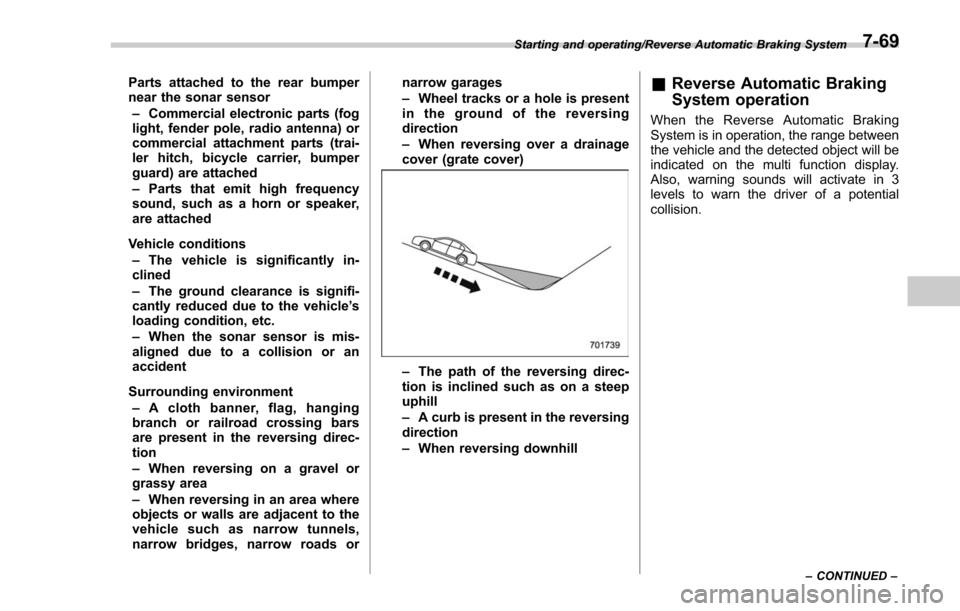
Parts attached to the rear bumper
near the sonar sensor– Commercial electronic parts (fog
light, fender pole, radio antenna) or
commercial attachment parts (trai-
ler hitch, bicycle carrier, bumper
guard) are attached
– Parts that emit high frequency
sound, such as a horn or speaker,
are attached
Vehicle conditions – The vehicle is significantly in-
clined
– The ground clearance is signifi-
cantly reduced due to the vehicle ’s
loading condition, etc.
– When the sonar sensor is mis-
aligned due to a collision or an
accident
Surrounding environment – A cloth banner, flag, hanging
branch or railroad crossing bars
are present in the reversing direc-
tion
– When reversing on a gravel or
grassy area
– When reversing in an area where
objects or walls are adjacent to the
vehicle such as narrow tunnels,
narrow bridges, narrow roads or narrow garages
–
Wheel tracks or a hole is present
in the ground of the reversing
direction
– When reversing over a drainage
cover (grate cover)
– The path of the reversing direc-
tion is inclined such as on a steep
uphill
– A curb is present in the reversing
direction
– When reversing downhill
& Reverse Automatic Braking
System operation
When the Reverse Automatic Braking
System is in operation, the range between
the vehicle and the detected object will be
indicated on the multi function display.
Also, warning sounds will activate in 3
levels to warn the driver of a potential
collision.
Starting and operating/Reverse Automatic Braking System
–CONTINUED –7-69
Page 593 of 634

Specifications/Fuses and circuits
&Fuse panel located in the engine compartment
A) Main fuse Fuse
panel Fuse
rating Circuit
1 30A .ABS unit
. Vehicle Dynamics Con-
trol unit
2 25A .Main fan (cooling fan)
3 25A .Sub fan (cooling fan)
4 Empty
5 25A .Audio
6 30A .Headlight (low beam)
7 15A .Headlight (high beam)
8 20A .Back-up
9 15A .Horn
10 25A .Rear window defogger
. Mirror heater
11 20A .Fuel pump
12 20A .Continuously variable
transmission control unit
13 7.5A .Engine control unit
14 15A .Turn and hazard warn-
ing flasher
15 15A .Tail and illumination re-
lay
16 7.5A .Alternator
12-14
Page 621 of 634

14-6Index
Rear seat.............................................................. 1-12
Headlight Beam leveler ....................................................... 3-102
Bulb replacement .................................................. 11-39
Bulb wattage ....................................................... 12-16
Control switch ........................................................ 3-93
Flasher ................................................................. 3-98
Indicator light ......................................................... 3-33
OFF delay function ................................................. 3-94
Welcome lighting function ....................................... 3-94
HID headlights .......................................................... 11-39
High beam assist function ........................................... 3-95
Indicator light ......................................................... 3-32
High beam indicator light ............................................ 3-32
High/low beam change (dimmer) .................................. 3-95
Hill descent control ..................................................... 7-42
Indicator light ......................................................... 3-33
Hill start assist .................................................. 7-50, 11-21
OFF indicator light .................................................. 3-23
To activate/deactivate ............................................. 7-50
Warning light ......................................................... 3-23
HomeLink
®.............................................................. 3-109
Hook Cargo tie-down ...................................................... 6-16
Convenient ............................................................ 6-13
Shopping bag ........................................................ 6-13
Towing and tie-down ............................................... 9-13
Horn ........................................................................\
3-118
Hose and connections ............................................... 11-12 I
Ignition switch
............................................................. 3-4
Light ...................................................................... 3-6
Illumination brightness control .................................... 3-101
Immobilizer ................................................................. 2-3
Indicator light (security indicator light) ........................ 3-30
Indicator light BSD/RCTA OFF ............................................. 3-34, 7-64
BSD/RCTA warning ........................................ 3-33, 7-63
Coolant temperature low .......................................... 3-17
Cruise control ........................................................ 3-32
Cruise control set ................................................... 3-32
Front fog light ......................................................... 3-33
Headlight ............................................................... 3-33
High beam ............................................................. 3-32
High beam assist .................................................... 3-32
Hill descent control ................................................. 3-33
Hill start assist OFF ................................................ 3-23
Immobilizer ............................................................ 3-30
Security ................................................................. 3-30
Select lever/Gear position ........................................ 3-31
SI-DRIVE .............................................................. 3-31
Steering responsive fog lights OFF ... ........................ 3-33
Turn signal ............................................................ 3-32
Vehicle Dynamics Control OFF ................................. 3-25
Vehicle Dynamics Control operation .......................... 3-25
X-mode ................................................................. 3-33
Information display ...................................................... 3-34
Inside mirror ............................................................ 3-107
Interior lights ............................................................... 6-2