2017 SUBARU FORESTER headlight system
[x] Cancel search: headlight systemPage 248 of 634

NOTE
.After manually changing the head-
light mode to the high beam, if you turn
on the high beam assist function,
return the light control switch to the
“ AUTO ”position.
. When manually changing the head-
light mode to the high beam, if you turn
the light control switch to the “
”
position, the instrument panel illumina-
tion, parking lights, front side marker
lights, rear side marker lights, tail lights
and license plate lights will be on.
! Tips for the high beam assist
system
. The high beam assist function recog-
nizes the condition surrounding the vehi-
cle based on the brightness of illumination
ahead of your vehicle, etc. Therefore, the
headlight mode may switch in some
situations that do not match to the driver ’s
sense.
. A bicycle or cargo cycle may not be
detected.
. Under the following situations, the
brightness of ambient illumination may
not be detected correctly and the high
beam assist function may not work prop-
erly. As a result, the glare of the high beam
may disturb the driving of an oncoming
vehicle or vehicle ahead. Also, the low beam mode may continue although there
are no oncoming vehicles and vehicles
ahead. In the such cases, change the
headlight mode manually.
–In bad weather (fog, snow, sand
storm, heavy rain, etc.)
– When the windshield glass is dirty
or fogged
– When the windshield is cracked or
damaged
– When the stereo camera is de-
formed or the stereo camera lenses
are dirty
– If there are lights similar to the
headlights or the tail lights in the
surrounding area
– When an oncoming vehicle or ve-
hicle ahead is driven without its head-
lights and tail lights on
– If the headlights of an oncoming
vehicle or the tail lights of a vehicle
ahead are dirty or discolored, or if the
light beams are not aimed correctly
– When a rapid change of brightness
continues while driving
– When driving on a road with many
ups and downs or uneven surfaces
– When driving on a road with many
curves
– When there are some objects that
reflect light strongly, such as a road
sign or a mirror in vehicle ahead –
When the rear part of the vehicle
ahead, such as a container, reflects
light strongly
– When the headlights of your vehicle
are damaged or dirty
– When your vehicle is tilted, such as
in case the vehicle has a flat tire or is
being towed
– Immediately after the engine has
started
. In the following conditions, the head-
light mode will not be automatically chan-
ged from the high beam to the low beam.
–When your vehicle passes an on-
coming vehicle suddenly in a blind
curve
– When another vehicle passes in
front of your vehicle
– When an oncoming vehicle or ve-
hicle ahead comes in and out of view
because of continuous curves, median
strips, roadside trees, etc.
. If the stereo camera detects the light of
the front fog lights of an oncoming vehicle,
the headlight mode may change from the
high beam to the low beam automatically.
. The headlight mode may change from
the high beam to the low beam, or the low
beam mode may continue, when affected
by a street light, traffic signal, illumination
of an advertisement board, or a reflective
object such as a road sign and signboard.
Instruments and controls/Light control switch
–CONTINUED –3-97
Page 249 of 634

Instruments and controls/Light control switch
.The timing of the change of headlight
mode may differ due to the following
factors.
–Color or brightness of the head-
lights of an oncoming vehicle or the tail
lights of a vehicle ahead
– The headlights of the oncoming
vehicle or the tail lights of the vehicle
ahead are covered with mud, snow,
etc.
– Movement and direction of an on-
coming vehicle or a vehicle ahead
– When the headlights of an oncom-
ing vehicle or the tail lights of a vehicle
ahead illuminate on only one side
– When the oncoming vehicle or
vehicle ahead is a motorcycle
– Conditions of a road (slope, curve,
road surface, etc.)
– Number of passengers and weight
of loaded cargo
– Limitation of the detection ability of
the stereo camera& Headlight flasher
CAUTION
Do not hold the lever in the flashing
position for more than just a few
seconds.
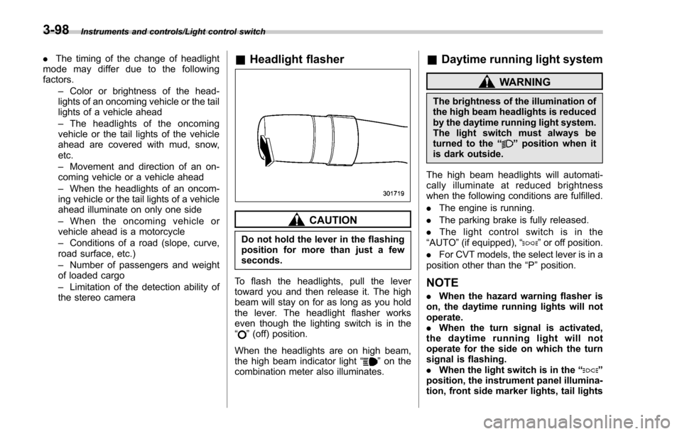
To flash the headlights, pull the lever
toward you and then release it. The high
beam will stay on for as long as you hold
the lever. The headlight flasher works
even though the lighting switch is in the
“
” (off) position.
When the headlights are on high beam,
the high beam indicator light “
”on the
combination meter also illuminates.
& Daytime running light system
WARNING
The brightness of the illumination of
the high beam headlights is reduced
by the daytime running light system.
The light switch must always be
turned to the “
”position when it
is dark outside.
The high beam headlights will automati-
cally illuminate at reduced brightness
when the following conditions are fulfilled.
. The engine is running.
. The parking brake is fully released.
. The light control switch is in the
“AUTO ”(if equipped), “
”or off position.
. For CVT models, the select lever is in a
position other than the “P”position.
NOTE
. When the hazard warning flasher is
on, the daytime running lights will not
operate.
. When the turn signal is activated,
the daytime running light will not
operate for the side on which the turn
signal is flashing.
. When the light switch is in the “
”
position, the instrument panel illumina-
tion, front side marker lights, tail lights
3-98
Page 250 of 634

and license plate lights are also illumi-
nated.
.For models with the auto on/off
headlights, while the light control
switch is in the “AUTO”position and
the system is activated to the auto-on
mode depending on the ambient light
level, the high beam headlights that
have illuminated at reduced brightness
turn off, and the low beam headlights
turn on alternatively. At this time, the
instrument panel illumination, front
side marker lights, tail lights and
license plate lights are also illuminated.
! Models with LED headlights
For models with LED headlights, the
parking lights are illuminated by the day-
time running light system.Steering Responsive Head-
light (SRH) (if equipped)
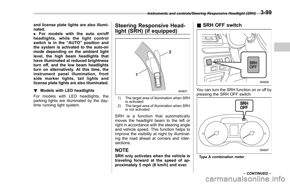
1) The target area of illumination when SRH is activated
2) The target area of illumination when SRH is not activated
SRH is a function that automatically
moves the headlight beam to the left or
right in accordance with the steering angle
and vehicle speed. This function helps to
improve the visibility at night by illuminat-
ing the road ahead at corners and inter-
sections.
NOTE
SRH only activates when the vehicle is
traveling forward at the speed of ap-
proximately 5 mph (8 km/h) and over.
&SRH OFF switch
You can turn the SRH function on or off by
pressing the SRH OFF switch.
Type A combination meter
Instruments and controls/Steering Responsive Headlight (SRH)
–CONTINUED –
3-99
Page 254 of 634

&Steering responsive fog
lights system (if equipped)
The steering responsive fog lights system
automatically turns the front fog light on
and off based on the steering angle and
vehicle speed when entering a curve or
driving on curved roads. The system is
intended to help prevent accidents by
enabling better visibility of curves ahead
and early recognition of any disabled
vehicles or other obstacles.
The front fog light on the inside of a curve
will turn on if all of the following conditions
are met.
. The light control switch is in the “
”
position, or the light control switch is in the
“AUTO ”position and the low beam head-
lights are turned on automatically
. The fog light switch is in the “
”
position
. The low beam mode is selected
. The select lever is in the “D”position or
the manual mode is selected
. The steering responsive fog lights
system has not been deactivated
. The operating conditions such as the
steering angle and vehicle speed are met
The front fog lights on both sides will turn
on as usual if all of the following conditions
are met. .
The light control switch is in either of
the following positions.
–in the “
”position
– in the “AUTO ”position and the low
beam headlights turn on automatically
. The fog light switch is in the “
”
position
. The low beam mode is selected
! Steering responsive fog lights OFF
switch
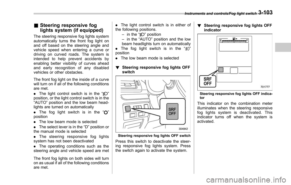
Steering responsive fog lights OFF switch
Press this switch to deactivate the steer-
ing responsive fog lights system. Press
the switch again to activate the system. !
Steering responsive fog lights OFF
indicator
Steering responsive fog lights OFF indica-
tor
This indicator on the combination meter
illuminates when the steering responsive
fog lights system is deactivated. This
indicator turns off when the system is
activated.
Instruments and controls/Fog light switch3-103
Page 413 of 634

Starting and operating/Starting and stopping the engine (models without push–button start system)
. When starting the engine, be sure
to sit in the driver ’s seat (except
when using the remote engine
start system).
NOTE
. Avoid rapid racing and rapid accel-
eration immediately after the engine
has started.
. For a short time after the engine has
started, the engine speed is kept high.
When the warm-up is completed, the
engine speed lowers automatically.
. On rare occasions, it may be difficult
to start the engine depending on the
fuel and the usage condition (repeated
driving of a distance in which the
engine has not warmed up sufficiently).
In such a case, it is recommended that
you change to a different brand of fuel.
. On rare occasions, transient knock-
ing may be heard from the engine when
the accelerator is operated rapidly
such as a rapid start-up and a rapid
acceleration. This is not a malfunction.
. The engine starts more easily when
the headlights, air conditioner and rear
window defogger are turned off.
. After the engine starts, the engine
speed will be kept high until the engine
has warmed up sufficiently. !
MT models
1. Apply the parking brake.
2. Turn off unnecessary lights and ac-
cessories.
3. Depress the clutch pedal to the floor
and shift the shift lever into neutral. Hold
the clutch pedal to the floor while starting
the engine.
The starter motor will only operate when
the clutch pedal is depressed fully to the
floor.
4. Turn the ignition switch to the “ON”
position and check the operation of the
warning and indicator lights. Refer to
“Warning and indicator lights ”F 3-13.
5. Turn the ignition switch to the “START”
position without depressing the accelera-
tor pedal. Release the key immediately
after the engine has started.
If the engine does not start, try the
following procedure.
(1) Turn the ignition switch to the
“OFF ”position and wait for at least
10 seconds. After checking that the
parking brake is firmly set, turn the
ignition switch to the “START”position
while depressing the accelerator pedal
slightly (approximately a quarter of the
full stroke). Release the accelerator
pedal as soon as the engine starts.
(2) If this fails to start the engine, turn the ignition switch back to the
“OFF”
position and wait for at least 10
seconds. Then fully depress the accel-
erator pedal and turn the ignition
switch to the “START”position. If the
engine starts, quickly release the
accelerator pedal.
(3) If this fails to start the engine, turn
the ignition switch again to the “OFF”
position. After waiting for 10 seconds
or longer, turn the ignition switch to the
“START ”position without depressing
the accelerator pedal.
(4) If the engine still does not start,
contact your nearest SUBARU dealer
for assistance.
6. Confirm that all warning and indicator
lights have turned off after the engine has
started. The fuel injection system auto-
matically lowers the idle speed as the
engine warms up.
! CVT models
1. Apply the parking brake.
2. Turn off unnecessary lights and ac-
cessories.
3. Shift the select lever to the “P”or “N
”
position (preferably the “P”position).
The
starter motor will only operate when
the select lever is at the “P”or “N”position.
4. Turn the ignition switch to the “ON”
7-10
Page 465 of 634

Starting and operating/BSD/RCTA
signal lever is operated toward the side in
which this light turned on, the indicator
light flashes to warn the driver of dangers.
When reversing the vehicle, the indicator
light flashes when the system detects a
vehicle approaching from either side.! BSD/RCTA approach indicator
light dimming function
When the headlights are turned on, the
brightness of the BSD/RCTA approach
indicator light will be reduced.
NOTE
. When affected by direct sunlight,
you may have difficulty recognizing
the BSD/RCTA approach indicator light.
. When affected by the headlight
beams from the vehicles behind, you
may have difficulty recognizing the
BSD/RCTA approach indicator light.
. While the illumination brightness
control dial is in the fully upward
position, even if the headlights are
turned on, the brightness of the BSD/
RCTA approach indicator light will not
be reduced. For details about the
illumination brightness control dial,
refer to “Illumination brightness con-
trol” F3-101. !
BSD/RCTA approach warning buz-
zer (only when reversing)
A warning buzzer sounds along with
flashing of the BSD/RCTA approach in-
dicator light to warn the driver of dangers.
The setting of the warning buzzer volume
can be changed by operating the multi
information display of the combination
meter. For details, refer to “BSD/RCTA”
F 3-43.
! Safety tips regarding the BSD/RCTA
approach indicator light/warning
buzzer
. In the following cases, operation of the
BSD/RCTA approach indicator light and
the warning buzzer may be delayed or the
system may fail to issue these warnings.
–Whenavehiclemovestothe
neighboring lane from a lane next to
the neighboring lane
– When driving on a steep incline or
on repeated sharp uphill and downhill
grades
– When going beyond a pass
– When both your vehicle and a
vehicle driving on a neighboring lane
are driving on the far side of each lane.
– When several narrowly-spaced ve-
hicles are approaching in a row
– In low radius bends (tight bends or when making turns at an intersection)
–
When there is a difference in height
between your lane and the neighbor-
ing lane
– Immediately after the BSD/RCTA is
activated by pressing the BSD/RCTA
OFF switch
– Immediately after the shift lever/
select lever is shifted to the “R ”
position
– When extremely heavy cargo is
loaded in the trunk or cargo area
. During reversing, operation of the BSD/
RCTA approach indicator light and the
warning buzzer may be delayed or the
system may fail to issue these warnings
under the following conditions.
–When backing out of an angled
parking space
– When a large-sized vehicle is
parked next to your vehicle (That
vehicle prevents the propagation of
radar waves.)
– When reversing on sloped roads
– When reversing at a high speed
7-62
Page 596 of 634

Wattage Bulb No.
1) High beam headlight/Daytime running light
(models with halogen light) 12V-60W HB3
2) Vanity mirror light 12V-2W –
3) Front turn signal light 12V-28W/8W
*17444NA
4) Low beam headlight (models with halogen light) 12V-55W H11
5) Front fog light
Models without steering responsive fog lights system 12V-19W H16
Models with steering responsive fog lights system 12V-55W H11
6) Map light 12V-8W–
7) Parking light (models with halogen light)
*212V-5W W5W
8) Dome light 12V-8W –
9) Front side marker light 12V-5W W5W
10) Door step light 12V-5W W5W
11 ) Cargo area light 12V-5W W5W
12) Tail light (This light is also used as the rear side marker light) 12V-5W W5W
13) Backup light 12V-16W W16W
14) Rear turn signal light 12V-21W WY21W
15) License plate light 12V-5W W5W Specifications/Bulb chart
–CONTINUED –
12-17
Page 617 of 634

14-2Index
A
Abbreviation................................................................... 3
ABS (Anti-lock Brake System) ..................................... 7-37
Warning light ......................................................... 3-21
Access key ................................................................. 2-9
Warning light ......................................................... 3-25
Accessories .............................................................. 11-38
Accessory power outlet ................................................. 6-9
Air cleaner element ................................................... 11-14
Air conditioner Automatic climate control .......................................... 4-7
Manual climate control .............................................. 4-8
Air filtration system ..................................................... 4-13
Air flow mode .............................................................. 4-8
Alarm system ............................................................ 2-25
All-Wheel Drive warning light ....................................... 3-23
Aluminum wheel ....................................................... 11-30
Cleaning ............................................................... 10-3
Antenna ...................................................................... 5-2
Anti-lock Brake System (ABS) ..................................... 7-37
Arming the system ..................................................... 2-26
Armrest ..................................................................... 1-11
Ashtray ..................................................................... 6-11
AT OIL TEMP warning light ......................................... 3-19
Audio aha
TMby HARMAN ................................................ 5-43
AM/FM radio ......................................................... 5-27
Antenna .................................................................. 5-2
AUX ..................................................................... 5-60
Base display audio set. ............................................. 5-3
Basic operation ...................................................... 5-17 Bluetooth audio
...................................................... 5-57
CD ....................................................................... 5-52
iPod ...................................................................... 5-55
Pandora
®.............................................................. 5-49
SiriusXM Satellite Radio .......................................... 5-36
STARLINK
TM7.0 Multimedia Plus audio set ................ 5-5
Steering switches for audio ...................................... 5-62
SUBARU STARLINK ............................................... 5-25
Unit setting ............................................................ 5-18
USB memory ......................................................... 5-54
Auto-dimming mirror/compass .......................... 3-108, 3-109
Automatic climate control .............................................. 4-7
Automatic headlight beam leveler ............................... 3-102
Warning light .......................................................... 3-32
Automatic Locking Retractor/Emergency Locking Retractor (ALR/ELR) ................................................ 1-17
B
Battery .................................................................... 11-36
Drainage prevention function ..................................... 2-7
Jump starting .......................................................... 9-9
Replacement (access key) ..................................... 11-45
Replacement (remote engine start transmitter) ........... 7-20
Replacement (transmitter) ...................................... 11-46
Bluetooth
®
Audio .................................................................... 5-57
Hands-free phone system ........................................ 5-70
Bluetooth
®settings ..................................................... 5-65
Registering/connecting Bluetooth®device .................. 5-65
Setting Bluetooth details .......................................... 5-68
Booster seat .............................................................. 1-36