Page 545 of 634

Maintenance and service/Air cleaner element
CAUTION
.Be careful not to spill engine
coolant when adding it. If coolant
touches the exhaust pipe, it may
cause a bad smell, smoke, and/or
a fire. If engine coolant gets on
the exhaust pipe, be sure to wipe
it off.
. Do not splash the engine coolant
over painted parts. The alcohol
contained in the engine coolant
may damage the paint surface.
! Changing the coolant
It may be difficult to change the coolant.
Have the coolant changed by your
SUBARU dealer if necessary.
The coolant should be changed according
to the maintenance schedule in the
“Warranty and Maintenance Booklet ”.
Air cleaner element
WARNING
Do not operate the engine with the
air cleaner element removed. The air
cleaner element not only filters
intake air but also stops flames if
the engine backfires. If the air
cleaner element is not installed
when the engine backfires, you
could be burned.
CAUTION
When replacing the air cleaner ele-
ment, use a genuine SUBARU air
cleaner element. If it is not used,
there is the possibility of causing a
negative effect to the engine.
The air cleaner element functions as a
filter screen. When the element is perfo-
rated or removed, engine wear will be
excessive and engine life shortened.
It is not necessary to clean or wash the air
cleaner element.
& Replacing the air cleaner
element
Replace the air cleaner element according
to the maintenance schedule in the
“Warranty and Maintenance Booklet ”. Un-
der extremely dusty conditions, replace it
more frequently. It is recommended that
you always use genuine SUBARU parts.
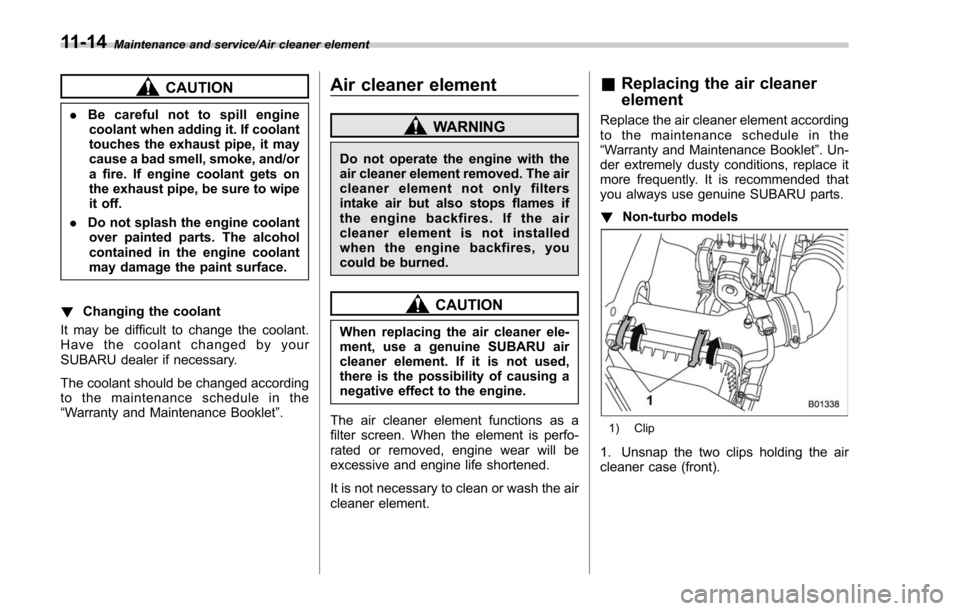
! Non-turbo models
1) Clip
1. Unsnap the two clips holding the air
cleaner case (front).
11-14
Page 547 of 634

Maintenance and service/Spark plugs
the air cleaner element.
3. Clean the inside of the air cleaner case
(both front and rear) with a damp cloth and
install a new air cleaner element.
4. To install the air cleaner case (rear),
insert the three projections on the air
cleaner case (rear) into the slits on the
air cleaner case (front).
5. Install in the reverse order of removal.
Spark plugs
It may be difficult to replace the spark
plugs. It is recommended that you have
the spark plugs replaced by your
SUBARU dealer.
The spark plugs should be replaced
according to the maintenance schedule
in the“Warranty and Maintenance Book-
let ”.
CAUTION
Make sure the cables are replaced in
the correct order.
& Recommended spark plugs
For the recommended spark plugs, refer
to“Electrical system ”F 12-10.
Drive belts
It is unnecessary to check the deflection of
the drive belt periodically because your
engine is equipped with an automatic belt
tension adjuster. However, replacement of
the belt should be done according to the
maintenance schedule in the “Warranty
and Maintenance Booklet ”. Consult your
SUBARU dealer for replacement.
If the drive belt is loose, cracked or worn,
contact your SUBARU dealer.
11-16
Page 551 of 634

Maintenance and service/Brake booster
Brake booster
If the brake booster does not operate as
described in the following, have it checked
by your SUBARU dealer.
1. With the engine off, depress the brake
pedal several times, applying the same
pedal force each time. The distance the
pedal travels should not vary.
2. With the brake pedal depressed, start
the engine. The pedal should move
slightly down to the floor.
3. With the brake pedal depressed, stop
the engine and keep the pedal depressed
for 30 seconds. The pedal height should
not change.
4. Start the engine again and run for
approximately one minute then turn it off.
Depress the brake pedal several times to
check the brake booster. The brake
booster operates properly if the pedal
stroke decreases with each depression.
Brake pedal
Check the brake pedal free play and
reserve distance according to the main-
tenance schedule in the“Warranty and
Maintenance Booklet ”.
&Checking the brake pedal
free play
1) 0.02 - 0.11 in (0.5 - 2.7 mm)
Stop the engine and firmly depress the
brake pedal several times. Lightly pull the
brake pedal up with one finger to check
the free play with a force of less than 2 lbf
(10 N, 1 kgf).
If the free play is not within proper
specification, contact your SUBARU deal-
er.
&Checking the brake pedal
reserve distance
1) More than 2.56 in (65 mm)
Depress the pedal with a force of approxi-
mately 66 lbf (294 N, 30 kgf) and measure
the distance between the upper surface of
the pedal pad and the floor.
When the measurement is smaller than
the specification, or when the pedal does
not operate smoothly, contact with your
SUBARU dealer.
11-20
Page 552 of 634

Clutch pedal (MT models)
Check the clutch pedal free play according
to the maintenance schedule in the
“Warranty and Maintenance Booklet”.
& Checking the clutch function
Check the clutch engagement and disen-
gagement.
1. With the engine idling, check that there
are no abnormal noises when the clutch
pedal is depressed, and that shifting into
1st or reverse feels smooth.
2. Start the vehicle by releasing the pedal
slowly to check that the engine and
transmission smoothly couple without
any sign of slippage.
&Checking the clutch pedal
free play
1) 0.16 - 0.43 in (4.0 - 11.0 mm)
Lightly depress the clutch pedal down with
your finger until you feel resistance, and
check the free play.
If the free play is not within proper
specification, contact your SUBARU deal-
er.
Hill start assist system
Ensure that the Hill start assist system
operates properly under the following
circumstances.
1. Stop the vehicle on an uphill grade by
depressing the brake pedal (all models)
and clutch pedal (MT models only), with
the engine running.
2. Make sure that the vehicle does not
move backward for several seconds after
the brake pedal is released.
3. Then make sure the vehicle starts
climbing the grade by following the normal
starting procedures.
If the Hill start assist system does not
operate as described above, contact your
SUBARU dealer.
Maintenance and service/Clutch pedal (MT models)11-21
Page 561 of 634

Maintenance and service/Aluminum wheels
&Wheel replacement
When replacing wheels due, for example,
to damage, make sure the replacement
wheels match the specifications of the
wheels that are fitted as standard equip-
ment. Replacement wheels are available
from SUBARU dealers.
WARNING
Use only those wheels that are
specified for your vehicle. Wheels
not meeting specifications could
interfere with brake caliper opera-
tion and may cause the tires to rub
against the wheel well housing dur-
ing turns. The resulting loss of
vehicle control could lead to an
accident.
NOTE
When any of the wheels are removed
and replaced for tire rotation or to
change a flat tire, always check the
tightness of the wheel nuts after driv-
ing approximately 600 miles (1,000 km).
If any nut is loose, tighten it to the
specified torque.
Aluminum wheels
Aluminum wheels can be scratched and
damaged easily. Handle them carefully to
maintain their appearance, performance,
and safety.
. When any of the wheels are removed
and replaced for tire rotation or to change
a flat tire, always check the tightness of
the wheel nuts after driving approximately
600 miles (1,000 km). If any nut is loose,
tighten it to the specified torque.
. Never apply oil to the threaded parts,
wheel nuts, or tapered surface of the
wheel.
. Never let the wheel rub against sharp
protrusions or curbs.
. When wheel nuts, balance weights, or
the center cap is replaced, be sure to
replace them with genuine SUBARU parts
designed for aluminum wheels.
Windshield washer fluid
CAUTION
Never use engine coolant as washer
fluid because it could cause paint
damage.
Windshield washer fluid warning light
(type A)
11-30
Page 568 of 634

1) Cap
2) Upper level
3) Lower level
It is unnecessary to periodically check the
battery fluid level or periodically refill with
distilled water.
However, if the battery fluid level is below
the lower level, remove the cap. Fill to the
upper level with distilled water.
CAUTION
Never use more than 10 amperes
when charging the battery because
it will shorten battery life.
Fuses
CAUTION
Never replace a fuse with one hav-
ing a higher rating or with material
other than a fuse because serious
damage or a fire could result.
The fuses are designed to melt during an
overload to prevent damage to the wiring
harness and electrical equipment. The
fuses are located in two fuse boxes.
One is located under the instrument panel
behind the fuse box cover on the driver ’s
seat side. To remove the cover, pull it out.
1) Spare fuses
The other one (main fuse box) is housed
in the engine compartment. Also, the
spare fuses are stored in the fuse box
cover.
The fuse puller is stored in the main fuse
Maintenance and service/Fuses
–CONTINUED –11-37
Page 569 of 634

Maintenance and service/Installation of accessories
box in the engine compartment.
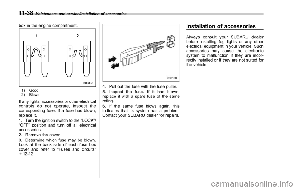
1) Good
2) Blown
If any lights, accessories or other electrical
controls do not operate, inspect the
corresponding fuse. If a fuse has blown,
replace it.
1. Turn the ignition switch to the“LOCK” /
“ OFF ”position and turn off all electrical
accessories.
2. Remove the cover.
3. Determine which fuse may be blown.
Look at the back side of each fuse box
cover and refer to “Fuses and circuits”
F 12-12.
4. Pull out the fuse with the fuse puller.
5. Inspect the fuse. If it has blown,
replace it with a spare fuse of the same
rating.
6. If the same fuse blows again, this
indicates that its system has a problem.
Contact your SUBARU dealer for repairs.
Installation of accessories
Always consult your SUBARU dealer
before installing fog lights or any other
electrical equipment in your vehicle. Such
accessories may cause the electronic
system to malfunction if they are incor-
rectly installed or if they are not suited for
the vehicle.
11-38
Page 580 of 634

Specifications..................................................... 12-2Dimensions........................................................ 12-2
Engine ............................................................... 12-3
Fuel ................................................................... 12-3
Engine oil .......................................................... 12-4
Manual transmission, front differential and rear differential gear oil ........................................... 12-7
Fluids ................................................................ 12-9
Engine coolant ................................................... 12-9
Electrical system .............................................. 12-10
Tires ................................................................ 12-10 Temporary spare tires
...................................... 12-10
Brake disc ....................................................... 12-11Fuses and circuits ........................................... 12-12Fuse panel located in the passenger
compartment ................................................. 12-12
Fuse panel located in the engine compartment ................................................. 12-14
Bulb chart......................................................... 12-16
Vehicle identification ....................................... 12-19
Specifications
12