2017 SUBARU FORESTER rear light
[x] Cancel search: rear lightPage 511 of 634

In case of emergency/Flat tires
17. When storing the spare tire after
repairing a flat tire, be sure to place the
spacer in the manner shown in the
illustration, and then tighten the bolt in
the rear side of the bracket.
WARNING
Never place a tire or tire changing
tools in the passenger compartment
after changing wheels. In a sudden
stop or collision, loose equipment
could strike occupants and cause
injury. Store the tire and all tools in
the proper place.
&Tire pressure monitoring
system (TPMS) (U.S.-spec.
models)
Low tire pressure warning light (type A)
Low tire pressure warning light (type B)
The tire pressure monitoring system pro-
vides the driver with a warning message
by sending a signal from a sensor that is
installed in each wheel when a tire
pressure is severely low relative to the
selected TPMS mode.
The tire pressure monitoring system will
activate only when the vehicle is driven at
speeds above 25 mph (40 km/h). Also,
this system may not react immediately to a
sudden drop in tire pressure (for example,
a blow-out caused by running over a
sharp object).
WARNING
If the low tire pressure warning light
illuminates while driving, never
brake suddenly and keep driving
straight ahead while gradually redu-
cing speed. Then slowly pull off the
road to a safe place. Otherwise an
accident involving serious vehicle
damage and serious personal injury
could occur.
Check the pressure for all four tires
and adjust the pressure to the COLD
tire pressure shown on the vehicle
placard on the door pillar on the
driver ’s side. If this light still illumi-
nates while driving after adjusting
the tire pressure, a tire may have
9-8
Page 527 of 634

Appearance care/Exterior care
Exterior care
&Washing
CAUTION
. When washing the vehicle, the
brakes may get wet. As a result,
the brake stopping distance will
be longer. To dry the brakes,
drive the vehicle at a safe speed
while lightly depressing the
brake pedal to heat up the
brakes.
. Do not wash the engine compart-
ment and area adjacent to it. If
water enters the engine air intake
or electrical parts, it will cause
engine trouble or a malfunction
of electrical equipment.
. When washing the inner fenders,
underbody, bumpers and pro-
truding objects such as exhaust
pipes and exhaust finishers, be
careful to avoid contact with any
sharp ends in order to prevent
injures.
. Do not use any organic solvents
when washing the surface of the
bulb assembly cover. However, if
a detergent with organic solvents
is used to wash the cover sur- face, completely rinse off the
detergent with water. Otherwise,
the cover surface may be da-
maged.
. Since your vehicle is equipped
with a rear wiper, automatic car-
wash brushes could become
tangled around it, damaging the
wiper arm and other compo-
nents. Ask the automatic car-
wash operator not to let the
brushes touch the wiper arm or
to fix the wiper arm on the rear
window glass with adhesive tape
before operating the machine.
NOTE
When having your vehicle washed in
an automatic car wash, make sure
beforehand that the car wash is of
suitable type.
The best way to preserve your vehicle’ s
beauty is frequent washing. Wash the
vehicle at least once a month to avoid
contamination by road grime.
Wash dirt off with a wet sponge and plenty
of lukewarm or cold water. Do not wash
the vehicle with hot water and in direct
sunlight.
Salt, chemicals, insects, tar, soot, tree sap, and bird droppings should be washed
off by using a light detergent, as required.
If you use a light detergent, make certain
that it is a neutral detergent. Do not use
strong soap or chemical detergents. All
cleaning agents should be promptly rinsed
off the surface and not allowed to dry
there. Rinse the vehicle thoroughly with
plenty of lukewarm water. Wipe the
remaining water off with a chamois or soft
cloth. Wear rubber gloves and use a hand
brush when washing down underbody,
inner fenders and suspension to remove
mud and dirt effectively.
!
Washing the underbody
Chemicals, salts and gravel used for
deicing road surfaces are extremely cor-
rosive, accelerating the corrosion of un-
derbody components, such as the exhaust
system, fuel and brake lines, brake
cables, floor pan and fenders, and sus-
pension.
Thoroughly flush the underbody and in-
side of the fenders with lukewarm or cold
water at frequent intervals to reduce the
harmful effects of such agents.
Mud and sand adhering to the underbody
components may accelerate their corro-
sion.
After driving off-road or on muddy or
sandy roads, wash the mud and sand off
10-2
Page 533 of 634

Maintenance and service
Tire replacement.............................................. 11-29
Wheel replacement ........................................... 11-30
Aluminum wheels............................................. 11-30
Windshield washer fluid .................................. 11-30
Replacement of wiper blades .......................... 11-32
Windshield wiper blade assembly ..................... 11-33
Windshield wiper blade rubber ......................... 11-33
Rear window wiper blade assembly .................. 11-34
Rear window wiper blade rubber ....................... 11-35
Battery............................................................... 11-36
Fuses ................................................................ 11-37
Installation of accessories ............................... 11-38 Replacing bulbs
............................................... 11-39
Headlights (models with LED headlights) .......... 11-39
Headlights (models with halogen headlights) .................................................... 11-39
Front turn signal light, front side marker light and parking light ........................................... 11-41
Front fog light (if equipped) .............................. 11-42
Rear combination lights ................................... 11-42
License plate light ........................................... 11-44
Other bulbs ..................................................... 11-44
Replacing key battery ...................................... 11-44Replacing battery of access key ....................... 11-45
Replacing transmitter battery ........................... 11-46
Page 553 of 634

Maintenance and service/Replacement of brake pad and lining
Replacement of brake pad
and lining
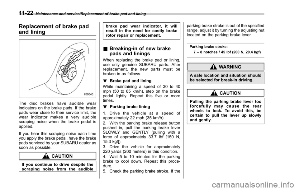
The disc brakes have audible wear
indicators on the brake pads. If the brake
pads wear close to their service limit, the
wear indicator makes a very audible
scraping noise when the brake pedal is
applied.
If you hear this scraping noise each time
you apply the brake pedal, have the brake
pads serviced by your SUBARU dealer as
soon as possible.
CAUTION
If you continue to drive despite the
scraping noise from the audiblebrake pad wear indicator, it will
result in the need for costly brake
rotor repair or replacement.
&
Breaking-in of new brake
pads and linings
When replacing the brake pad or lining,
use only genuine SUBARU parts. After
replacement, the new parts must be
broken in as follows.
! Brake pad and lining
While maintaining a speed of 30 to 40
mph (50 to 65 km/h), step on the brake
pedal lightly. Repeat this five or more
times.
! Parking brake lining
1. Drive the vehicle at a speed of
approximately 22 mph (35 km/h).
2. With the parking brake release button
pushed in, pull the parking brake lever
SLOWLY and GENTLY (pulling with a
force of approximately 33.7 lbf [150 N,
15.3 kgf]).
3. Drive the vehicle for approximately
220 yards (200 meters) in this condition.
4. Wait 5 to 10 minutes for the parking
brake to cool down. Repeat this proce-
dure.
5. Check the parking brake stroke. If the parking brake stroke is out of the specified
range, adjust it by turning the adjusting nut
located on the parking brake lever.
Parking brake stroke:
7–8 notches / 45 lbf (200 N, 20.4 kgf)
WARNING
A safe location and situation should
be selected for break-in driving.
CAUTION
Pulling the parking brake lever too
forcefully may cause the rear
wheels to lock. To avoid this, be
certain to pull the lever up slowly
and gently.
11-22
Page 555 of 634

Maintenance and service/Tires and wheels
temperature outside. By way of example,
the following table shows the required tire
pressures that correspond to various out-
side temperatures when the temperature
in the garage is 608F (15.6 8C).
Example:
Tire size: P205/55R16 89V and
P205/50R17 88V
Standard tire pressures:
Front: 33 psi (230 kPa, 2.3 kgf/cm
2)
Rear: 32 psi (220 kPa, 2.2 kgf/cm2)
Garage temperature: 60 8F (15.6 8C)
Outside
temperature Adjusted pressure
[psi (kPa, kgf/cm2)]
Front Rear
30 8F( −18C) 36 (250, 2.5) 35 (240, 2.4)
10 8F( −12 8C) 38
(260, 2.6) 37
(255, 2.55)
−10 8F( −23 8C) 40
(275, 2.75) 39 (270, 2.7)
If the low tire pressure warning light
illuminates when you drive the vehicle in
cold outside air after adjusting the tire
pressures in a warm garage, re-adjust the
tire pressures using the method described
above. Then, increase the vehicle speed
to at least 25 mph (40 km/h) and check to
see that the low tire pressure warning light
turns off a few minutes later. If the low tire pressure warning light does not turn off,
the tire pressure monitoring system may
not be functioning normally. In this event,
go to a SUBARU dealer to have the
system inspected as soon as possible.
While the vehicle is driven, friction be-
tween tires and the road surface causes
the tires to warm up. After illumination of
the low tire pressure warning light, any
increase in the tire pressures caused by
an increase in the outside air temperature
or by an increase in the temperature in the
tires can cause the low tire pressure
warning light to turn off.
System resetting is necessary when the
wheels are changed (for example, a
switch to snow tires) and new TPMS
valves are installed on the newly fitted
wheels. Have this work performed by a
SUBARU dealer following wheel replace-
ment.
It may not be possible to install TPMS
valves on certain wheels that are on the
market. Therefore, if you change the
wheels (for example, a switch to snow
tires), use wheels that have the same part
number as the standard-equipment
wheels. Without four operational TPMS
valve/sensors on the wheels, the TPMS
will not fully function and the warning light
on the combination meter will illuminatesteadily after blinking for approximately
one minute.
When a tire is replaced, adjustments are
necessary to ensure continued normal
operation of the tire pressure monitoring
system. As with wheel replacement, there-
fore, you should have the work performed
by a SUBARU dealer.
WARNING
If the low tire pressure warning light
does not illuminate briefly after the
ignition switch is turned ON or the
light illuminates steadily after blink-
ing for approximately one minute,
you should have your Tire Pressure
Monitoring System checked at a
SUBARU dealer as soon as possi-
ble.
If this light illuminates while driving,
never brake suddenly. Instead, per-
form the following procedure. Other-
wise an accident involving serious
vehicle damage and serious perso-
nal injury could occur.
1) Keep driving straight ahead while
gradually reducing speed.
2) Slowly pull off the road to a safe place.
If this light still illuminates while
11-24
Page 567 of 634

Maintenance and service/Battery
ends. If the rubber is not retained properly,
the wiper may scratch the rear window
glass.
5. Install the wiper blade assembly to the
wiper arm. Make sure that it locks in place.
6. Hold the wiper arm by hand and slowly
lower it in position.Battery
WARNING
.Before beginning work on or near
any battery, be sure to extinguish
all cigarettes, matches, and light-
ers. Never expose a battery to an
open flame or electric sparks.
Batteries give off a gas which is
highly flammable and explosive.
. For safety, in case an explosion
does occur, wear eye protection
or shield your eyes when work-
ing near any battery. Never lean
over a battery.
. Do not let battery fluid contact
eyes, skin, fabrics, or paint be-
cause battery fluid is a corrosive
acid. If battery fluid gets on your
skin or in your eyes, immediately
flush the area with water thor-
oughly. Seek medical help imme-
diately if acid has entered the
eyes.
If battery fluid is accidentally
swallowed, immediately drink a
large amount of milk or water,
and seek medical attention im-
mediately.
. To lessen the risk of sparks, remove rings, metal watchbands,
and other metal jewelry. Never
allow metal tools to contact the
positive battery terminal and any-
thing connected to it WHILE you
are at the same time in contact
with any other metallic portion of
the vehicle because a short cir-
cuit will result.
. Keep everyone including children
away from the battery.
. Charge the battery in a well-
ventilated area.
. Battery posts, terminals and re-
lated accessories contain lead
and lead compounds, chemicals
known to the State of California
to cause cancer and reproductive
harm. Batteries also contain
other chemicals known to the
State of California to cause can-
cer.
Wash hands after handling.
11-36
Page 573 of 634

Maintenance and service/Replacing bulbs
Front turn signal light (models with LED
headlight)
Front side marker light and parking light
(models with halogen headlight)
1) Front side marker light
2) Parking light
Front side marker light (models with LED
headlight)
1) Front side marker light
2. Turn the socket counterclockwise and
pull it out.
3. Pull out the bulb from the socket and
replace the bulb with a new one.
4. To install the socket to the headlight
assembly, turn it clockwise until it clicks.
5. Install the electrical connector to the
clip.
&Front fog light (if equipped)
It may be difficult to replace the bulbs.
Have the bulbs replaced by your SUBARU
dealer if necessary.
&Rear combination lights
NOTE
The stop light is an LED (Light Emitting
Diode) type. Consult your SUBARU
dealer for replacement.
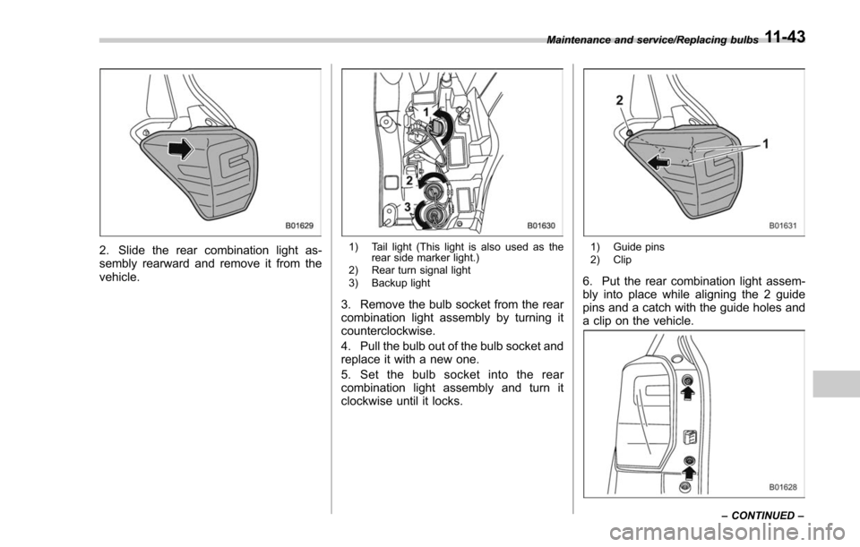
1. Using a Phillips screwdriver, remove
the upper and lower screws that secure
the rear combination light assembly.
11-42
Page 574 of 634

2. Slide the rear combination light as-
sembly rearward and remove it from the
vehicle.1) Tail light (This light is also used as therear side marker light.)
2) Rear turn signal light
3) Backup light
3. Remove the bulb socket from the rear
combination light assembly by turning it
counterclockwise.
4. Pull the bulb out of the bulb socket and
replace it with a new one.
5. Set the bulb socket into the rear
combination light assembly and turn it
clockwise until it locks.
1) Guide pins
2) Clip
6. Put the rear combination light assem-
bly into place while aligning the 2 guide
pins and a catch with the guide holes and
a clip on the vehicle.
Maintenance and service/Replacing bulbs
–CONTINUED –11-43