2017 SEAT IBIZA ST warning
[x] Cancel search: warningPage 139 of 248
Air conditioning
Air conditioning
He atin
g,
ventilation and cool-
ing
General notes Read the additional information carefully
›› ›
page 39
Pollution filter
The pollution filter (a combined particulate
filter and active carbon filter) serves as a bar-
rier against impurities in the outside air, in-
cluding dust and pollen.
For the climate control system to work with
maximum efficiency, the pollution filter must
be replaced at the specified intervals in the
Maintenance Programme.
If the filter loses efficiency prematurely due
to use in areas reaching very high pollution
levels, the pollen filter must be changed
more frequently than stated in the Service
Schedule. WARNING
Reduced visibility through the windows in-
cr e
ases the risk of serious accidents.
● Always ensure that all windows are free of
ice and sno
w, and that they are not fogged, so as to maintain good visibility of everything
outs
ide.
● The m
aximum heat output required to de-
fros
t windows as quickly as possible is only
available when the engine has reached its
normal running temperature. Only drive when
you have good visibility.
● Always ensure that you use the heating
syst
em, fresh air system, air conditioner and
the heated rear window to maintain good visi-
bility to the outside.
● Never leave the air recirculation on for a
long period of time. If
the cooling system is
switched off and air recirculation mode
switched on, the windows can mist over very
quickly, considerably limiting visibility.
● Switch air recirculation mode off when it is
not requir
ed. WARNING
Stuffy or used air will increase fatigue and re-
duce driv er c
oncentration possibly resulting
in a serious accident.
● Never leave the fresh air fan turned off or
use the air rec
irculation for long periods of
time; the air in the vehicle interior will not be
refreshed. CAUTION
● If y
ou suspect that the air conditioner is
damaged, switch it off with the A/C button to prevent further damage and have it checked
by
a s
pecialised workshop.
● Repairs to the air conditioner require spe-
cia
list knowledge and special tools. There-
fore, we recommend you to take the vehicle
to a specialised workshop. Note
● If the humidity and t
emperature outside the
vehicle are high, condensation can drip off
the evaporator in the cooling system and
form a pool underneath the vehicle. This is
normal and does not indicate a leak.
● Keep the air intake slots in front of the
winds
creen free of snow, ice and leaves to en-
sure heating and cooling are not impaired,
and to prevent the windows from misting
over.
● The air from the vents flows through the ve-
hicle int
erior and is extracted by slots in the
luggage compartment designed for this pur-
pose. Therefore, you should avoid obstruct-
ing these slots with any kind of object.
● The air conditioner operates most effective-
ly with the w
indows and the sliding/tilting
sunroof* closed. However, if the temperature
inside the vehicle is excessive because of the
sun, the air inside can be cooled faster by
opening the windows for a short time.
● Do not smoke while air recirculation mode
is on, a
s smoke drawn into the air condition-
ing system leaves residue on the evaporator,
producing a permanent unpleasant odour. » 137
Technical data
Advice
Operation
Emergencies
Safety
Page 141 of 248
Air conditioning
Air distributionSymbol ››› page 139
CMain air output through out-
lets
1, 2
5
1, 2, 5
3, 4
Outlets
3 and
4 can be closed or opened
separ at
ely using the slats and the air flow di-
rected as required.
Heating and fresh air
Contr o
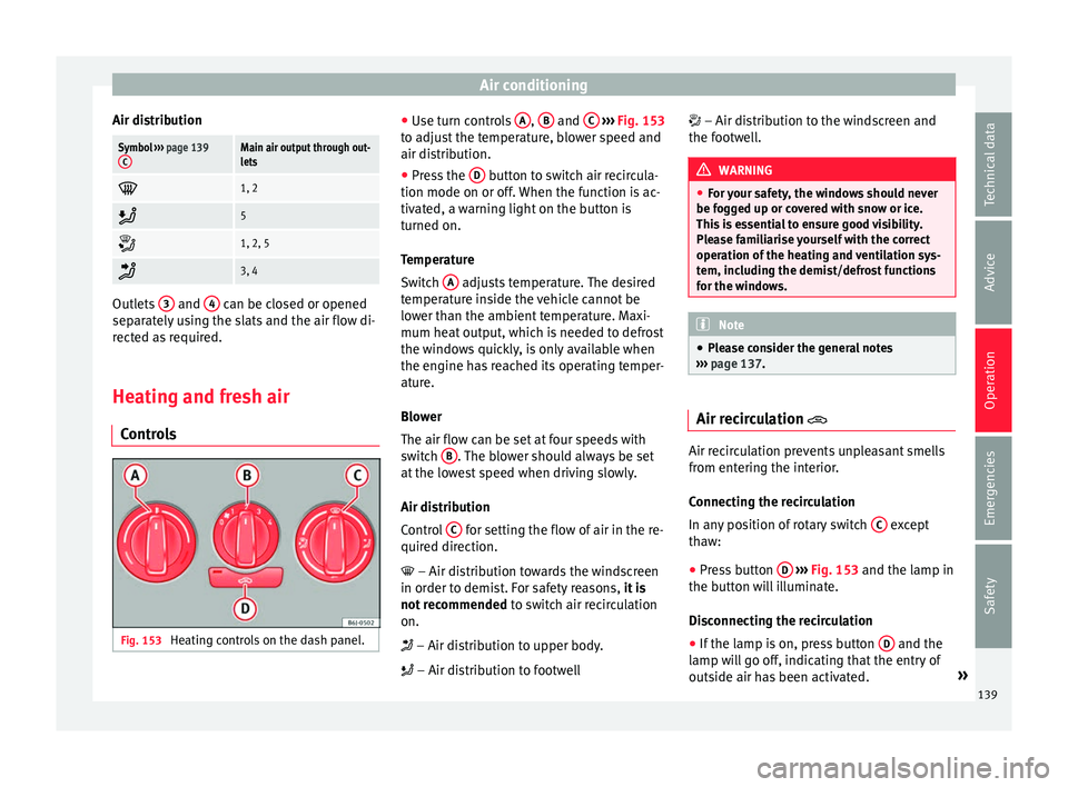
ls Fig. 153
Heating controls on the dash panel. ●
Use t
urn c
ontrols A ,
B and
C
› ››
Fig. 153
t o a
djust the temperature, blower speed and
air distribution.
● Press the D button to switch air recircula-
tion mode on or off .
When the f
unction is ac-
tivated, a warning light on the button is
turned on.
Temperature
Switch A adjusts temperature. The desired
t emper
at
ure inside the vehicle cannot be
lower than the ambient temperature. Maxi-
mum heat output, which is needed to defrost
the windows quickly, is only available when
the engine has reached its operating temper-
ature.
Blower
The air flow can be set at four speeds with
switch B . The blower should always be set
at the lo
w
est speed when driving slowly.
Air distribution
Control C for setting the flow of air in the re-
quir ed dir
ection.
– Air distribution towards the windscreen
in order to demist. For safety reasons, it is
not recommended to switch air recirculation
on.
– Air distribution to upper body.
– Air distribution to footwell – Air distribution to the windscreen and
the footw
ell. WARNING
● For y
our safety, the windows should never
be fogged up or covered with snow or ice.
This is essential to ensure good visibility.
Please familiarise yourself with the correct
operation of the heating and ventilation sys-
tem, including the demist/defrost functions
for the windows. Note
● Ple a
se consider the general notes
››› page 137. Air recirculation
Air recirculation prevents unpleasant smells
fr
om ent
erin
g the interior.
Connecting the recirculation
In any position of rotary switch C except
th a
w:
● Pr
ess button D
› ›
›
Fig. 153 and the lamp in
the button will illuminate.
Disconnecting the recirculation
● If the lamp is on, press button D and the
l amp w
i
ll go off, indicating that the entry of
outside air has been activated. »
139
Technical data
Advice
Operation
Emergencies
Safety
Page 142 of 248
Operation
If the rotary switch C
› ››
Fig. 153
i s in the
thaw position, the recirculation flap will al-
ways be open and air will always enter from
the outside.
If the rotary switch C is switched from any
po s
ition t
o the thaw position, recirculation
will be automatically deactivated. WARNING
● In air rec ir
culation mode, no cold air from
the outside enters the vehicle interior. The
windows can quickly fog over if the heating is
switched off. Therefore, never leave the air re-
circulation mode switched on for a long time
(risk of accident). Vehicle ventilation or heating
Ventilating the vehicle interior
– Turn the temperature selector ››
›
Fig. 153
A anticlockwise.
– Turn blower switch B to any of the head
settin g
s
1-4.
– Set the airflow to the desired direction us-
ing air dis
tribution control C .
– Open the relevant air outlets. Interior heating
– Turn the temperature selector ››
›
Fig. 153
A clockwise to select the desired tempera-
t ur
e.
– T
urn blower switch B to any of the head
settin g
s
1-4.
– Set the airflow to the desired direction us-
ing air dis
tribution control C .
– Open the relevant air outlets.
D efr
o
sting the windscreen
– Turn the temperature selector ›››
Fig. 153
A clockwise to reach the maximum tem-
per at
ur
e.
– Turn the blower switch B to setting 4.
– Turn air distribution control to .
– Close outlet 3 .
– Open and turn outlet 4 towards the side
w indo
w
s.
Keeping the windscreen and the side win-
dows demisted
– Turn the temperature selector ›››
Fig. 153
A to the heating area.
– Turn blower switch B to any of the head
settin g
s
2-3.
– Turn air distribution control to .
– Close outlets 3 –
Open and t urn outl
ets
4 towards side win-
do w
s.
Onc
e the windows are demisted and as a pre-
ventive measure, the control C can be set in
po s
ition
, thus obtaining greater comfort
while preventing the windows from misting
again.
Heating
Maximum heat output, which is needed to
defrost the windows quickly, is only available
when the engine has reached its operating
temperature. Note
Remember that the temperature of the engine
coo l
ant should be optimum to ensure that the
heating system functions correctly (except in
vehicles fitted with additional heating*). 140
Page 143 of 248
Air conditioning
Air conditioning* C ontr
o
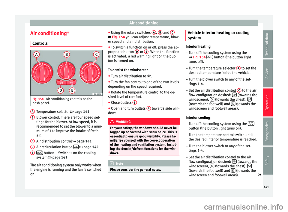
ls Fig. 154
Air conditioning controls on the
d a
sh p
anel. Temperature selector
››
›
page 141
Blower control. There are four speed set-
tings for the blower. At low speed, it is
recommended to set the blower to a mini-
mum of 1 to improve the intake of fresh
air.
Air distribution control ››› page 141
Air recirculation button
› ›
› p
age 142
A/C button – Switches on the cooling
sy s
t
em ››› page 141
The air conditioning system only works when
the engine is running and the fan is switched
on. A B
C
D
E ●
Us
in
g the rotary switches A ,
B and
C ›››
Fig. 154 y ou c
an a djust temperature, blow-
er speed and air distribution.
● To switch a function on or off, press the ap-
propriat
e button D or
E . When the function
i s
activ
ated, a red warning light on the but-
ton is turned on.
To demist the windscreen
● Turn air distribution to .
● Turn the fan control to one of the two levels
depending on the speed r
equired.
● Rotate the temperature control to the de-
sired l
evel of comfort.
● Close outlets 3 ●
Open and turn outlets 4 towards side win-
do w
s. WARNING
For your safety, the windows should never be
fog g
ed up or covered with snow or ice. This is
essential to ensure good visibility. Please fa-
miliarise yourself with the correct operation
of the heating and ventilation system, includ-
ing the demist/defrost functions for the win-
dows. Note
Please consider the general notes. Vehicle interior heating or cooling
sy
s
t
em Interior heating
– Turn off the cooling system using the
›› ›
Fig. 154 A/C button (the button light
turn s
off).
– Turn the temperature selector A to set the
des ir
ed temperature inside the vehicle.
– Turn the blower switch to any of the set-
tings
1-4.
– Set the air distribution control C to the air
flo w c
onfigur
ation desired: (towards the
w ind
s
creen), (towards the chest),
(towards the footwell) and
(towards the
w ind
s
creen and footwell areas).
Interior cooling
– Turn off the cooling system using the A/C button (the button light turns on).
– Turn the temperature control switch until
the de s
ir
ed interior temperature is reached.
– Turn the blower switch to any of the set-
tings
1-4.
– Set the air distribution control to the air
flow configur
ation desired: (towards the
w ind
s
creen), (towards the chest),
(towards the footwell) and
(towards the
w ind
s
creen and footwell areas). »
141
Technical data
Advice
Operation
Emergencies
Safety
Page 144 of 248
Operation
Heating
M ax
imum he
at output, which is needed to
defrost the windows quickly, is only available
when the engine has reached its operating
temperature.
Coolant system
When the air conditioning is switched on, the
temperature and the air humidity go down.
This way, if the outside humidity is extreme,
the air conditioning prevents the misting of
the windows and therefore, comfort is im-
proved.
If the air conditioning does not work, this
may be due to the following reasons:
● The engine is stationary.
● The fan blower is switched off.
● The outside temperature is lower than ap-
prox
imately +3°C (+37°F).
● The air conditioning system compressor
has
been temporarily switched off because of
an increased engine coolant temperature.
● The air conditioner fuse is faulty.
● Another fault in the vehicle. Have the air
conditioning c
hecked by a specialised work-
shop. Air recirculation
Air recirculation prevents unpleasant smells,
e.g. when p
a
ssing through a tunnel or in
queuing traffic, from entering the interior.
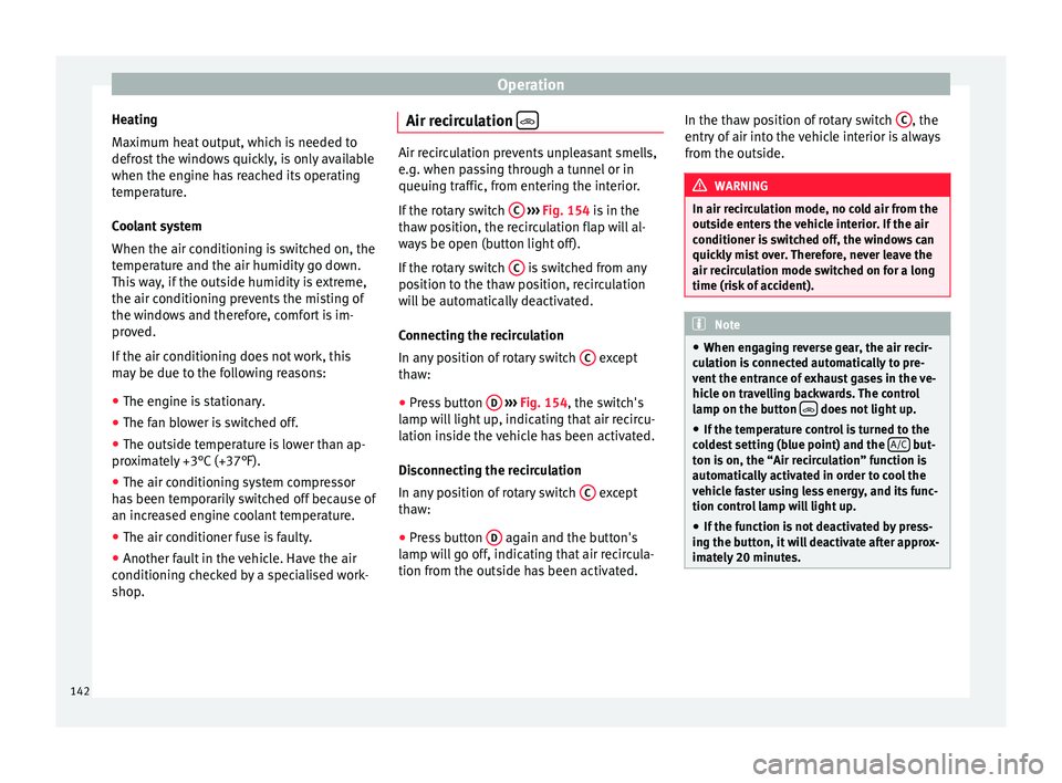
If the rotary switch C
››› Fig. 154 i
s in the
thaw position, the recirculation flap will al-
ways be open (button light off).
If the rotary switch C is switched from any
pos ition t
o the thaw position, recirculation
will be automatically deactivated.
Connecting the recirculation
In any position of rotary switch C except
th a
w:
● Pr
ess button D
› ›
› Fig. 154
, the switch's
lamp will light up, indicating that air recircu-
lation inside the vehicle has been activated.
Disconnecting the recirculation
In any position of rotary switch C except
th a
w:
● Pr
ess button D again and the button's
l amp w
i
ll go off, indicating that air recircula-
tion from the outside has been activated. In the thaw position of rotary switch
C , the
entr y
of
air into the vehicle interior is always
from the outside. WARNING
In air recirculation mode, no cold air from the
outs ide ent
ers the vehicle interior. If the air
conditioner is switched off, the windows can
quickly mist over. Therefore, never leave the
air recirculation mode switched on for a long
time (risk of accident). Note
● When eng agin
g reverse gear, the air recir-
culation is connected automatically to pre-
vent the entrance of exhaust gases in the ve-
hicle on travelling backwards. The control
lamp on the button does not light up.
● If the temperature control is turned to the
co l
dest setting (blue point) and the A/C but-
ton i s
on, the “Air recirculation” function is
automatically activated in order to cool the
vehicle faster using less energy, and its func-
tion control lamp will light up.
● If the function is not deactivated by press-
ing the butt
on, it will deactivate after approx-
imately 20 minutes. 142
Page 146 of 248
Operation
● Pr e
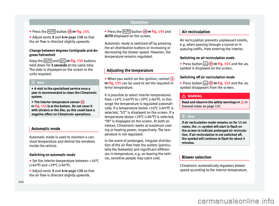
s
s the AUTO button
13
› ››
Fig. 155
.
● Adju
st vents 3 and 4 ›››
page 138 so that
the air flow is directed slightly upwards.
Change between degrees Centigrade and de-
grees Fahrenheit
Keep the AUTO and
A/C
› ››
Fig. 155
b
uttons
held down for 2 seconds at the same time.
The data is displayed on the screen in the
units required. Note
● A v i
sit to the specialised service once a
year is recommended to clean the Climatronic
system.
● The interior temperature sensor 11›››
Fig. 155 is at
the bottom. Do not cover it
with stickers or the like, as this could have a
negative effect on Climatronic operations. Automatic mode
Automatic mode is used to maintain a con-
s
t
ant
temperature and demist the windows
inside the vehicle.
Switching on automatic mode
● Set the interior temperature between +16°C
(+64°F) and +29°C (+84°F).
● Adjus
t vents 3 and 4 ›››
page 138 so that
the air flow is directed slightly upwards. ●
Pres
s the AUTO button
13
› ››
Fig. 155
and
AUTO di
splayed on the screen.
Automatic mode is switched off by pressing
the air distribution buttons or increasing or
decreasing the blower speed. However, the
temperature remains regulated.
Adjusting the temperature ●
When you switch on the ignition, control 1 ›››
Fig. 155 can be u sed t
o set the required in-
terior temperature.
It is possible to select interior temperatures
from +16°C (+64°F) to +29°C (+84°F). In this
range the temperature is regulated automati-
cally. If a temperature below +16°C (+64°F) is
selected, “LO” is displayed on the screen. If a
temperature above +29°C (+84°F) is selected,
“HI” is displayed on the screen. At both ex-
tremes, Climatronic works at maximum cool-
ing or heating power, respectively. The tem-
perature is not regulated.
In the event of prolonged, irregular distribu-
tion of the air flow from the outlets (particu-
larly the footwells) and significant differen-
ces in temperature, e.g. on leaving the vehi-
cle, sensitive people may catch cold. Air recirculation Air recirculation prevents unpleasant smells,
e.g. when p
a
ssing through a tunnel or in
queuing traffic, from entering the interior.
Switching on air recirculation mode
● Press button
17
››› Fig. 155 and the
symbol is displayed on the screen.
Switching off air recirculation mode
● Press button
17
› ›
› Fig. 155
and the
symbol disappears from the screen. WARNING
Read and observe the safety warnings ›››
in
Genera l
notes on page 137. Note
If air recirculation mode remains on for 15 mi-
nute s, the
symbol will start to flash on
the screen to indicate prolonged air recircula-
tion. If air recirculation is not switched off,
the symbol will continue to flash for about 5
minutes. Blower selection
Climatronic automatically regulates blower
s
peed ac
c
ording to the interior temperature.
144
Page 147 of 248
Driving
It is possible, however, to set the blower
s peed t
o s
uit requirements.
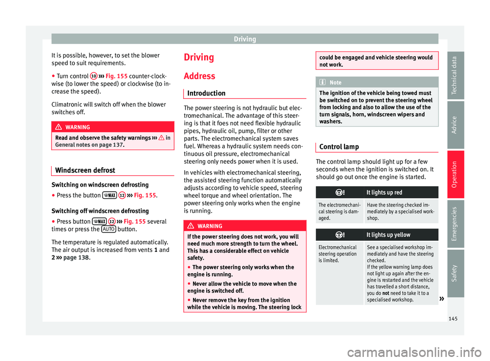
● Turn control 10
› ››
Fig. 155
c
ounter-clock-
wise (to lower the speed) or clockwise (to in-
crease the speed).
Climatronic will switch off when the blower
switches off. WARNING
Read and observe the safety warnings ›››
in
Genera l
notes on page 137. Windscreen defrost
Switching on windscreen defrosting
●
Press the button
12
› ›
›
Fig. 155.
Switching off windscreen defrosting
● Press button
12
› ›
›
Fig. 155 several
times or press the AUTO button.
The t emper
at
ure is regulated automatically.
The air output is increased from vents 1 and
2 ›››
page 138. Driving
Ad dr
e
ss
Introduction The power steering is not hydraulic but elec-
tromec
h
anical. The advantage of this steer-
ing is that it foes not need flexible hydraulic
pipes, hydraulic oil, pump, filter or other
parts. The electromechanical system saves
fuel. Whereas a hydraulic system needs con-
tinuous oil pressure, electromechanical
steering only needs power when it is used.
In vehicles with electromechanical steering,
the assisted steering function automatically
adjusts according to vehicle speed, steering
wheel torque and wheel orientation. The
power steering only works when the engine
is running. WARNING
If the power steering does not work, you will
need much mor e s
trength to turn the wheel.
This has a considerable effect on vehicle
safety.
● The power steering only works when the
engine is
running.
● Never allow the vehicle to move when the
engine is
switched off.
● Never remove the key from the ignition
while the
vehicle is moving. The steering lock could be engaged and vehicle steering would
not w
ork. Note
The ignition of the vehicle being towed must
be sw itc
hed on to prevent the steering wheel
from locking and also to allow the use of the
turn signals, horn, windscreen wipers and
washers. Control lamp
The control lamp should light up for a few
sec
ond
s
when the ignition is switched on. It
should go out once the engine is started.
It lights up red
The electromechani-
cal steering is dam-
aged.Have the steering checked im-
mediately by a specialised work-
shop.
It lights up yellow
Electromechanical
steering operation
is limited.See a specialised workshop im-
mediately and have the steering
checked.
If the yellow warning lamp does
not light up again after the en-
gine is restarted and the vehicle
has travelled a short distance,
you do not need to take it to a
specialised workshop.
» 145
Technical data
Advice
Operation
Emergencies
Safety
Page 148 of 248
Operation
It lights up yellow
The 12-volt battery
was disconnected
and has been recon-
nected.Take the vehicle for a short run
at 15-20 km/h (9-12 mph).
It flashes yellow
The steering column
is tight.Turn the wheel a little to both
sides.
The steering column
does not unlock or
lock.Remove the key from the ignition
and switch the ignition back on.
If necessary, check the messag-
es displayed on the instrument
panel display.
Do not drive on if
the steering
column remains locked after the
ignition has been switched on.
Seek specialist assistance. WARNING
If the warning lamps and the corresponding
mes s
ages are ignored when they light up, the
vehicle may stall in traffic and cause acci-
dents and severe injuries.
● Never ignore the warning lamps or messag-
es.
● Stop the
vehicle at the next opportunity
and in a safe p
lace. Note
Failure to heed the control lamps and corre-
spondin g t
ext messages when they light up
may result in damage to the vehicle. Information relating to different vehi-
cl
e pr
ocesses. In order to make the vehicle more difficult to
st
e
al, you should always lock the steering be-
fore leaving the vehicle.
Mechanical steering lock
The steering column is locked when the key
is removed from the ignition lock and the ve-
hicle is stationary.
Activating the steering lock
● Park the vehicle ››
›
page 149.
● Remove the ignition key.
● Turn the steering wheel slightly until the
steerin
g lock has engaged.
Deactivating the steering lock
● Turn the steering wheel slightly to release
the lock.
● Inser
t the key in the ignition lock.
● Hold the steering wheel in this position
and switc
h on the ignition. Electromechanical steering
In vehic
les with electromechanical steering,
the assisted steering function automatically
adjusts according to vehicle speed, steering
wheel torque and wheel orientation. The
power steering only works when the engine
is running.
You should take into account that you will
need considerably more power than normal
to steer the vehicle if the power steering is
not working correctly or at all.
Power-assisted steering
Power-assisted steering helps the driver in
critical situations. In counter-steering, it as-
sists by applying additional torque ››› .
WARNING
Power-assisted steering, together with the
ESC, help s
the driver to control vehicle steer-
ing in critical situations. However, the driver
is ultimately responsible for steering the ve-
hicle at all times. Power-assisted steering
does not remove this responsibility. 146