2017 SEAT IBIZA ST warning
[x] Cancel search: warningPage 130 of 248
Operation
Adjusting or disassembling the head
r e
s
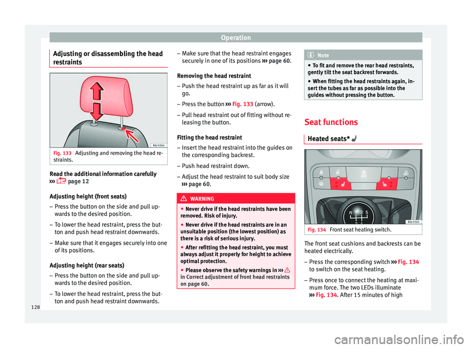
traints Fig. 133
Adjusting and removing the head re-
s tr
aints. Read the additional information carefully
› ›
›
page 12
Adjusting height (front seats)
– Press the button on the side and pull up-
ward
s to the desired position.
– To lower the head restraint, press the but-
ton and pu
sh head restraint downwards.
– Make sure that it engages securely into one
of its po
sitions.
Adjusting height (rear seats)
– Press the button on the side and pull up-
ward
s to the desired position.
– To lower the head restraint, press the but-
ton and pu
sh head restraint downwards. –
Make s
ure that the head restraint engages
securely in one of its positions ››› page 60.
Removing the head restraint – Push the head restraint up as far as it will
go.
– Pr
ess the button ›››
Fig. 133 (arrow).
– Pull head restraint out of fitting without re-
lea
sing the button.
Fitting the head restraint
– Insert the head restraint into the guides on
the corre
sponding backrest.
– Push head restraint down.
– Adjust the head restraint to suit body size
›››
page 60. WARNING
● Never driv e if
the head restraints have been
removed. Risk of injury.
● Never drive if the head restraints are in an
uns
uitable position (the lowest position) as
there is a risk of serious injury.
● After refitting the head restraint, you must
alwa
ys adjust it properly for height to achieve
optimal protection.
● Please observe the safety warnings in ›››
in Correct adjustment of front head restraints
on pag
e 60
. Note
● To fit and r
emove the rear head restraints,
gently tilt the seat backrest forwards.
● When fitting the head restraints again, in-
sert the t
ubes as far as possible into the
guides without pressing the button. Seat functions
Heat ed se
ats* Fig. 134
Front seat heating switch. The front seat cushions and backrests can be
he
at
ed el
ectrically.
– Press the corresponding switch ›››
Fig. 134
to switch on the seat heating.
– Press once to connect the heating at maxi-
mum forc
e. The two LEDs illuminate
››› Fig. 134. After 15 minutes of high
128
Page 132 of 248

Operation
WARNING
● Ple a
se be careful when folding back the
backrest! Injuries can be caused if the seat
height is adjusted without due care and at-
tention.
● Do no trap or damage seat belts when rais-
ing the bac
krest.
● After raising the backrest, check it has en-
gaged pr
operly in position. Do this by pulling
on the central seat belt or directly on the
backrest and check that the position lever is
in the neutral position.
● The three point automatic seat belt only
works
correctly when the backrest of the cen-
tral seat is correctly engaged. Transport and practical
equipment
Pr actic
a
l equipment
Glove compartment Fig. 137
Passenger side: glove compartment. Fig. 138
Glove compartment: storage com-
p ar tment
for instruction manual. The compartment can be opened by pulling
the l
ev
er ›
›› Fig. 137.
This compartment can hold documents in A4
format, a water bottle of 1.5 L, etc.
Depending on the vehicle equipment, the CD
player is located in the glove compartment.
Separate operating instructions are enclosed
for this equipment in the corresponding In-
struction Manual. WARNING
Always keep the storage compartment cover
clo sed whi
le the vehicle is in motion in order
to reduce the risk of injury caused by a sud-
den braking or by an accident. Storage compartment on the driver
s
ide Fig. 139
Compartment on the driver side130
Page 133 of 248
Transport and practical equipment
There is a storage compartment on the driver
s ide
St or
age compartment under the front
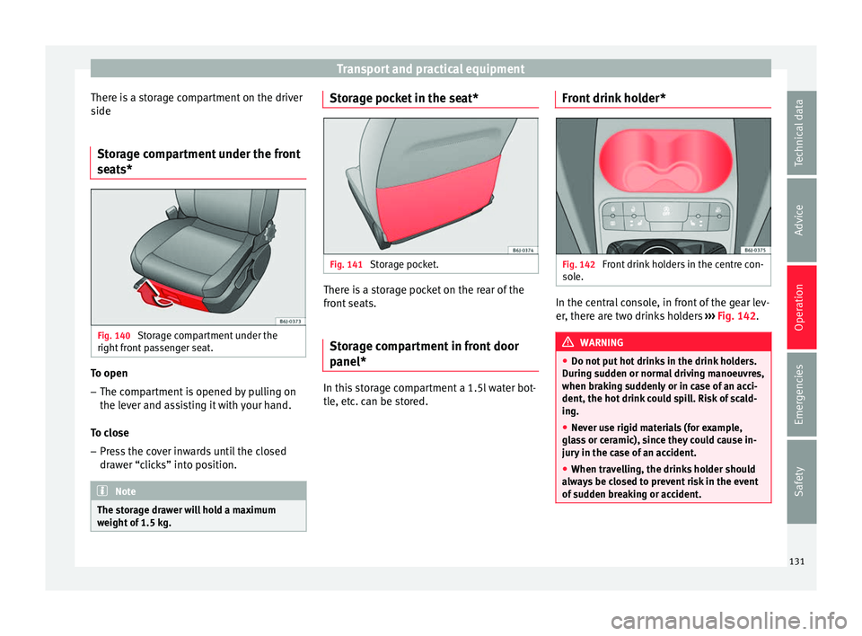
seats* Fig. 140
Storage compartment under the
right fr
ont
passenger seat. To open
– The compartment is opened by pulling on
the l ev
er and a
ssisting it with your hand.
To close – Press the cover inwards until the closed
draw
er “clicks” into position. Note
The storage drawer will hold a maximum
weight of
1.5 kg. Storage pocket in the seat*
Fig. 141
Storage pocket. There is a storage pocket on the rear of the
fr
ont
se
ats.
Storage compartment in front door
panel* In this storage compartment a 1.5l water bot-
tl
e, et
c
. can be stored. Front drink holder* Fig. 142
Front drink holders in the centre con-
so l
e. In the central console, in front of the gear lev-
er
, ther
e ar
e two drinks holders ››› Fig. 142. WARNING
● Do not p ut
hot drinks in the drink holders.
During sudden or normal driving manoeuvres,
when braking suddenly or in case of an acci-
dent, the hot drink could spill. Risk of scald-
ing.
● Never use rigid materials (for example,
glas
s or ceramic), since they could cause in-
jury in the case of an accident.
● When travelling, the drinks holder should
alwa
ys be closed to prevent risk in the event
of sudden breaking or accident. 131
Technical data
Advice
Operation
Emergencies
Safety
Page 134 of 248
Operation
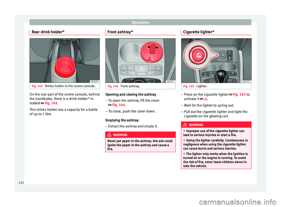
Rear drink holder* Fig. 143
Drinks holder in the centre console. On the rear part of the centre console, behind
the h
andbr
ak
e, there is a drink holder* in-
stalled ››› Fig. 143.
This drinks holder has a capacity for a bottle
of up to 1 litre. Front ashtray* Fig. 144
Front ashtray. Opening and closing the ashtray
– To open the ashtray, lift the cover
› ›
›
Fig. 144.
– To close, push the cover down.
Emptying the a
shtray
– Extract the ashtray and empty it. WARNING
Never put paper in the ashtray. Hot ash could
ignite the p aper in the a
shtray and cause a
fire. Cigarette lighter*
Fig. 145
Lighter. –
Press on the cigarette lighter ››
›
Fig. 145 to
activate it ››› .
– Wait for the lighter to spring out.
– Pull out the cigarette lighter and light the
cig
ar
ette on the glowing coil. WARNING
● Improper u se of
the cigarette lighter can
lead to serious injuries or start a fire.
● Using the lighter carefully. Carelessness or
negligenc
e when using the cigarette lighter
can cause burns and serious injuries.
● The lighter only works when the ignition is
turned on or the engine i
s running. To avoid
the risk of fire, never leave children alone in-
side the vehicle. 132
Page 135 of 248
Transport and practical equipment
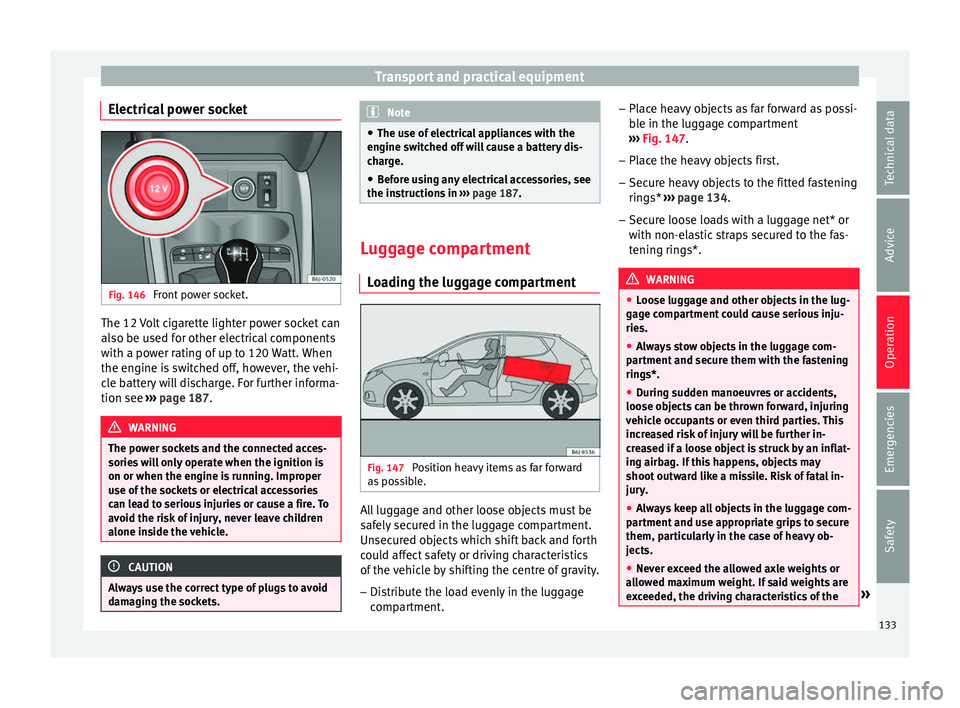
Electrical power socket Fig. 146
Front power socket. The 12 Volt cigarette lighter power socket can
al
so be u
sed f
or other electrical components
with a power rating of up to 120 Watt. When
the engine is switched off, however, the vehi-
cle battery will discharge. For further informa-
tion see ››› page 187. WARNING
The power sockets and the connected acces-
sories w
ill only operate when the ignition is
on or when the engine is running. Improper
use of the sockets or electrical accessories
can lead to serious injuries or cause a fire. To
avoid the risk of injury, never leave children
alone inside the vehicle. CAUTION
Always use the correct type of plugs to avoid
dam agin
g the sockets. Note
● The use of el
ectrical appliances with the
engine switched off will cause a battery dis-
charge.
● Before using any electrical accessories, see
the instruction
s in ››› page 187. Luggage compartment
Lo a
ding the luggage compartment Fig. 147
Position heavy items as far forward
a s
po
ssible. All luggage and other loose objects must be
s
af
ely
secured in the luggage compartment.
Unsecured objects which shift back and forth
could affect safety or driving characteristics
of the vehicle by shifting the centre of gravity.
– Distribute the load evenly in the luggage
compar
tment. –
Place he
avy objects as far forward as possi-
ble in the luggage compartment
››› Fig. 147.
– Place the heavy objects first.
– Secure heavy objects to the fitted fastening
rings* ›
›› page 134.
– Secure loose loads with a luggage net* or
with non-ela
stic straps secured to the fas-
tening rings*. WARNING
● Loo se lug
gage and other objects in the lug-
gage compartment could cause serious inju-
ries.
● Always stow objects in the luggage com-
partment
and secure them with the fastening
rings*.
● During sudden manoeuvres or accidents,
loose ob
jects can be thrown forward, injuring
vehicle occupants or even third parties. This
increased risk of injury will be further in-
creased if a loose object is struck by an inflat-
ing airbag. If this happens, objects may
shoot outward like a missile. Risk of fatal in-
jury.
● Always keep all objects in the luggage com-
partment
and use appropriate grips to secure
them, particularly in the case of heavy ob-
jects.
● Never exceed the allowed axle weights or
allo
wed maximum weight. If said weights are
exceeded, the driving characteristics of the » 133
Technical data
Advice
Operation
Emergencies
Safety
Page 136 of 248
Operation
vehicle may change, leading to accidents,
injuries
and d
amage to the vehicle.
● Please note that the centre of gravity may
shift when tr
ansporting heavy objects; this
may affect vehicle handling and lead to an ac-
cident. Therefore, it is essential to adjust
your speed and driving style accordingly, to
avoid accidents.
● Never leave your vehicle unattended, espe-
cia
lly when the rear lid is open. Children
could climb into the luggage compartment,
closing the door behind them; they will be
trapped and run the risk of death.
● Never allow children to play in or around
the vehic
le. Close and lock all the doors and
rear lid when you leave the vehicle. Before
you lock the vehicle, make sure that there are
no adults or children in the vehicle.
● Please observe the notes on the ›››
page 56. CAUTION
Hard objects on the rear shelf could chafe
again s
t the wires of the heating element in
the heated rear window and cause damage. Note
● The tyr e pr
essure must be adjusted accord-
ing to the load. When necessary check the
tyre pressures on the label located on the in-
side fuel tank flap ››› page 210.
● Air circulation in the vehicle helps reduce
foggin
g of the windows. Used air escapes through ventilation slits in the side trim of
the lugg
ag
e compartment. Ensure that the
ventilation slots are never covered.
● Straps for securing the load to the fasten-
ing ring
s* are commercially available from ac-
cessory shops. Fastening rings*
Fig. 148
Location of fastening rings in lug-
g ag
e c
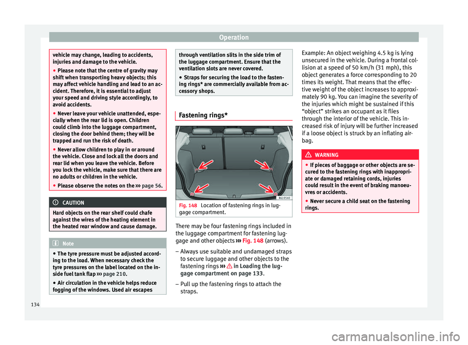
ompartment. There may be four fastening rings included in
the lug
g
ag
e compartment for fastening lug-
gage and other objects ››› Fig. 148 (arrows).
– Always use suitable and undamaged straps
to secur
e luggage and other objects to the
fastening rings ››› in Loading the lug-
g ag
e c
ompartment on page 133.
– Pull up the fastening rings to attach the
strap
s. Example: An object weighing 4.5 kg is lying
unsec
ured in the vehicle. During a frontal col-
lision at a speed of 50 km/h (31 mph), this
object generates a force corresponding to 20
times its weight. That means that the effec-
tive weight of the object increases to approxi-
mately 90 kg. You can imagine the severity of
the injuries which might be sustained if this
“object” strikes an occupant as it flies
through the interior of the vehicle. This in-
creased risk of injury will be further increased
if a loose object is struck by an inflating air-
bag. WARNING
● If piec e
s of baggage or other objects are se-
cured to the fastening rings with inappropri-
ate or damaged retaining cords, injuries
could result in the event of braking manoeu-
vres or accidents.
● Never secure a child seat on the fastening
rings. 134
Page 137 of 248
Transport and practical equipment
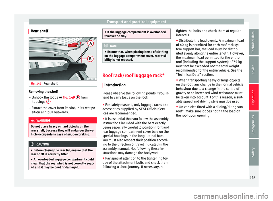
Rear shelf Fig. 149
Rear shelf. Removing the shelf
–
Unhook the loops ››
› Fig. 149 B from
hou s
in
gs A .
– Extract the cover from its slot, in its rest po-
sition and p
u
ll outwards. WARNING
Do not place heavy or hard objects on the
re ar shelf
, because they will endanger the ve-
hicle occupants in case of sudden braking. CAUTION
● Bef or
e closing the rear lid, ensure that the
rear shelf is correctly fitted.
● An overloaded luggage compartment could
mean that
the rear shelf is not correctly seat-
ed and it may be bent or damaged. ●
If the lug g
age compartment is overloaded,
remove the tray. Note
● En sur
e that, when placing items of clothing
on the luggage compartment cover, rear visi-
bility is not reduced. Roof rack/roof luggage rack*
Intr oduction Please observe the following points if you in-
t
end t
o c
arry loads on the roof:
● For safety reasons, only luggage racks and
acce
ssories supplied by SEAT Official Serv-
ices are recommended.
● It is essential that you follow the assembly
instruction
s included with the bars exactly,
being especially careful to position front and
rear luggage compartment cover bars on the
special housings in the longitudinal bars.
You must also respect their position accord-
ing to the direction of travel indicated in the
assembly manual. Not following these in-
structions may damage the bodywork.
● Pay special attention to the tightening tor-
que of the attac
hment bolts and check them
following a short journey. If necessary, re- tighten the bolts and check them at regular
interv
als.
● Distribute the load evenly. A maximum load
of 40 k
g is permitted for each roof rack sys-
tem support bar, the load must be distrib-
uted evenly along the entire length. However,
the maximum load permitted for the entire
roof (including the support system) of 75 kg
must not be exceeded nor the total weight
recommended for the entire vehicle. See the
“Technical Data” section.
● When transporting heavy or large objects
on the roof, an
y change in the normal vehicle
behaviour due to a change in the centre of
gravity or an increased wind resistance must
be taken into account. For this reason, a suit-
able speed and driving style must be used.
● On vehicles fitted with a sliding/tilting sun-
roof*, mak
e sure it does not hit the load on
the roof upon opening.
135
Technical data
Advice
Operation
Emergencies
Safety
Page 138 of 248
Operation
Attach the cross bars of the roof carri-
er sy s
t
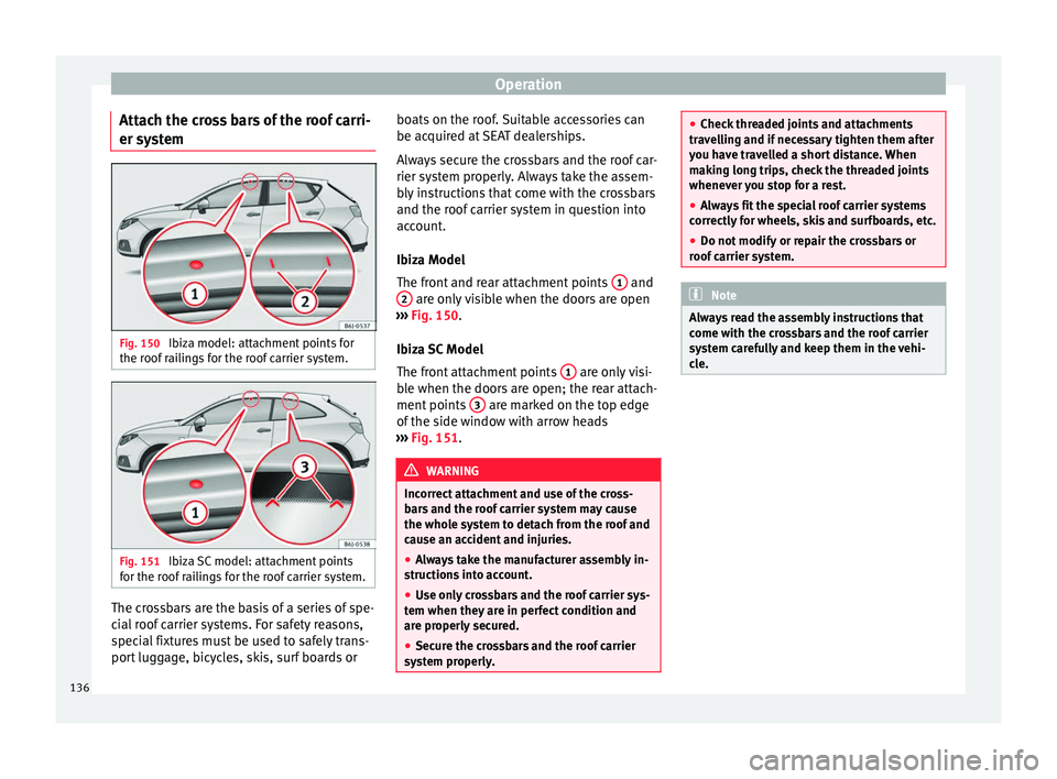
em Fig. 150
Ibiza model: attachment points for
the r oof
r
ailings for the roof carrier system. Fig. 151
Ibiza SC model: attachment points
f or the r
oof
railings for the roof carrier system. The crossbars are the basis of a series of spe-
c
i
al
roof carrier systems. For safety reasons,
special fixtures must be used to safely trans-
port luggage, bicycles, skis, surf boards or boats on the roof. Suitable accessories can
be acquired at
SEAT dealerships.
Always secure the crossbars and the roof car-
rier system properly. Always take the assem-
bly instructions that come with the crossbars
and the roof carrier system in question into
account.
Ibiza Model
The front and rear attachment points 1 and
2 are only visible when the doors are open
› ›
›
Fig. 150.
Ibiza SC Model
The front attachment points 1 are only visi-
b l
e when the door
s are open; the rear attach-
ment points 3 are marked on the top edge
of the s
ide w
indow with arrow heads
››› Fig. 151. WARNING
Incorrect attachment and use of the cross-
bar s
and the roof carrier system may cause
the whole system to detach from the roof and
cause an accident and injuries.
● Always take the manufacturer assembly in-
structions
into account.
● Use only crossbars and the roof carrier sys-
tem when they ar
e in perfect condition and
are properly secured.
● Secure the crossbars and the roof carrier
syst
em properly. ●
Check thr
eaded joints and attachments
travelling and if necessary tighten them after
you have travelled a short distance. When
making long trips, check the threaded joints
whenever you stop for a rest.
● Always fit the special roof carrier systems
correctly
for wheels, skis and surfboards, etc.
● Do not modify or repair the crossbars or
roof c
arrier system. Note
Always read the assembly instructions that
c ome w ith the c
rossbars and the roof carrier
system carefully and keep them in the vehi-
cle. 136