Page 233 of 320

Driver assistance systems
DCC continuously adapts the suspension to
the c ondition of
the r
oad and current driving
conditions, according to the pre-set pro-
gramme.
Steering is also adapted in the “Sport” pro-
gramme.
ProgrammeDriving recommendations
“COMFORT” C
Adjust it to the most comfortable set-
ting, for example, driving on surfaces
in poor condition, or making long
trips.
“NORMAL”Balanced setting, suitable, for exam-
ple, for day-to-day use.
“SPORT” SSport setting for sporty style driving Select a program
● Switch the ignition on.
● Press the C S butt
on r
epeatedly until the
desired programme is displayed.
The “NORMAL” programme is active when
neither the C nor S buttons are lit up. WARNING
Switching the dynamic chassis control sys-
tem on whi l
e the vehicle is in motion could
divert your attention from the traffic and
cause accidents. WARNING
Adjusting the suspension can change driving
proper tie
s. Dynamic chassis control must
never lead to any kinds of risk.
● Adapt your speed and driving style at all
times t
o suit visibility, weather, road and traf-
fic conditions. Note
If the dynamic chassis control does not oper-
ate a s
described in this chapter, go to an au-
thorised workshop and request it be checked. Note
In case of a fault in the dynamic chassis con-
tro l, the b
uttons C and S will so indicate. A
fault could the affect driving comfort. Have
the system checked by a specialised work-
shop. Tyre monitoring systems
Intr oduction The tyre monitor indicator monitors the tyre
pr
e
s
sure of each wheel during driving using
the ABS sensors. The ABS sensors monitor
the tyre tread perimeter and vibrations of
each tyre. The tyre monitor indicator warns
the driver if it detects a considerable drop in
tyre pressure of one or several tyres while driving. Loss of tyre pressure will be indica-
ted by
the indicator as well as an audible
warning and sometimes a text message on
the dash panel display. When you open the
driver door, you will find a label indicating
the tyre pressure recommended by the manu-
facturer for the maximum vehicle load for
each tyre approved for the vehicle in ques-
tion. By pressing the adjustment button on
the tyre monitoring indicator, you may
change the reference pressure for the tyres
so that the tyre pressure coincides with ac-
tual pressure ››› page 233.
Suitable use of the adjustment button
››› page 233. WARNING
Unsuitable handling of the wheels and tyres
ma y
lead to sudden tyre pressure losses, to
tread separation or even to a blow-out.
● Check tyre pressures regularly and ensure
they are m
aintained at the pressures indica-
ted. If the tyre pressure is too low, the tyres
could overheat, resulting in tread detachment
or even burst tyres.
● Tyre pressure should be that indicated on
the label when the ty
res are cold at all times
››› page 288.
● Regularly check the cold inflation pressure
of the tyr
es. If necessary, change the tyre
pressure of the vehicle tyres while they are
cold. » 231
Technical data
Advice
Operation
Emergencies
Safety
Page 234 of 320

Operation
●
Re gu
larly check your tyres for damage and
wear.
● Never exceed the maximum permitted
speed or loa
ds specified for the type of tyre
fitted on your vehicle. WARNING
Incorrect use of the tyre monitoring indicator
b utt on c
ould result in the indicator giving er-
roneous messages or prevented from indicat-
ing the danger caused by a defective tyre
››› page 233. CAUTION
● The tyr e
valves may be damaged if the cap
is not in place. Check that the caps are identi-
cal to the standard caps and have been cor-
rectly tightened. Do not use metal caps
››› page 233.
● Do not damage the valves when changing
the tyre
s ››› page 233. For the sake of the environment
Under-inflated tyres lead to increased fuel
con s
umption and tyre wear. Note
● Do not on ly
rely on the tyre monitoring sys-
tem. Regularly check your tyres to ensure
that the tyre pressure is correct and that the
tyres are not damaged due to puncture, cuts, tears and impacts/dents. Remove objects
from the ty
r
es only when the tyres have not
been pierced by these.
● The tyre monitoring system is set to the
tyre pr
essure recommended by the manufac-
turer and indicated on the label ››› Fig. 251. Elements of the tyre monitoring indi-
cat
or
Tyre monitoring indicator with button.
See ››› page 233.
Control lamp on the instrument panel.
SET button on the centre console.
Monitoring the tread of all tyres using ABS sensors
(indirect measurement).
Adjustable medium and full-load tyre pressures.
Button to update the system when the tyre pressure is
changed. Control lamp
Blinks or lights up
The tyre pres-
sure of a wheel
has dropped
considerably in
relation to the
pressure set by
the driver
››› page 233. Stop the vehicle!
Reduce your
speed immediately! Stop the vehicle
safely as soon as possible. Avoid
sudden manoeuvres and braking!
Check all tyres and pressures. Re-
place any damaged tyres.
System malfunc-
tion.
Consult a specialised workshop if
the tyre pressure is correct and the
lamp remains lit after switching the
ignition off and back on again. Have
the system checked there. Several warning and control lamps light up
f
or a f
ew sec
onds when the ignition is switch-
ed on, signalling that the function is being
verified. They will switch off after a few sec-
onds. WARNING
Observe the safety warnings ›››
in Control
and warnin g l
amps on page 105. WARNING
When the tyres are inflated at different pres-
sur e
s or at a pressure that is too low then a
tyre may be damaged resulting in a loss of
control of the vehicle and a serious or fatal
accident. 232
Page 235 of 320

Driver assistance systems
●
If the w arnin
g lamp lights up, stop im-
mediately and check the tyres.
● If the tyres are inflated at different pres-
sure
s or if a tyre pressure is too low, this will
increase tyre wear, negatively affecting vehi-
cle stability and increasing braking distan-
ces.
● If tyres are inflated at different pressures or
a tyre pr
essure is too low, a tyre may be dam-
aged and burst resulting in a loss of control
of the vehicle.
● The driver is responsible for ensuring that
all
of the vehicle tyres are correctly inflated
to the right pressure. The recommended tyre
pressure is indicated on the label ››› Fig. 251.
● The tyre monitoring system can only oper-
ate corr
ectly if all of the tyres are inflated to
the correct pressure when cold.
● Driving with tyres at the wrong pressure
can dam
age them and result in an accident.
Ensure that the tyre pressures of all the tyres
correspond to the vehicle load.
● Before starting a journey, always inflate
tyre
s to the correct pressure.
● If tyre pressure is too low then the tyre is
subj
ect to greater forces and it may be heated
to such an extent that the tread can rupture
and the tyre will burst.
● With an overloaded vehicle at high speed,
the tyre
s can overheat and burst resulting in
a loss of vehicle control.
● Tyre pressures which are too high or too
low reduc
e the useful life of the tyre, affect-
ing vehicle performance. ●
If a ty r
e has not been “punctured” and does
not have to be changed immediately, drive to
the nearest specialised workshop at a moder-
ate speed and have the tyre checked and in-
flated to the correct pressure. Tyre monitoring indicator
Fig. 228
Detailed view of the centre console:
b utt
on f
or the tyre pressure monitoring indi-
cator The tyre monitor indicator compares wheel
r
ev
o
lutions and, with this information, the
tread of each wheel using the ABS sensors. If
the tread of a wheel is changed, the tyre
monitoring indicator will indicate as such on
the instrument panel. The wheel tread
changes when:
● Tyre pressure is insufficient
● Tyre structure is damaged ●
The vehic
le is unbalanced because of a
load
● If the wheels on an axle are subject to a
heavier lo
ad (e.g. when towing a trailer).
● The vehicle is fitted with snow chains
● The wheel on one axle is changed
There ma
y be a delay in the reaction of the
tyre monitoring indicator or it may not in-
dicate anything under certain circumstances
(e.g. sports driving, snow-covered or un-
paved roads).
Adaptation of the tyre monitoring indicator
On adjusting tyre pressure or changing one
or more wheels, the ››› Fig. 228 button on the
tyre monitoring indicator must be kept press-
ed down, with the ignition on, until an audi-
ble warning is heard. Do the same, for exam-
ple, when the front and rear wheels are swap-
ped ››› Fig. 250.
If the wheels are subjected to an excessive
load (towing a trailer, heavy load), the tyre
pressure must be increased to the maximum
recommended pressure ››› page 284. Press
the tyre monitoring indicator button to con-
firm the new pressure value. Note
An incorrect warning may be given when
sno w c
hains are in use because the chains in-
crease the tread of the wheel. 233
Technical data
Advice
Operation
Emergencies
Safety
Page 236 of 320

Operation
Towing bracket device
Driv in
g w
ith a trailer
Introduction Always be aware of the legal requirements for
eac
h c
ountry to drive with a trailer and to use
a tow hitch.
Your car is intended mainly for transporting
passengers however, it can also be used to
tow a trailer provided that it is fitted with the
necessary equipment. The additional load
has an effect on the useful life, fuel con-
sumption and the vehicle performance and,
in some cases, reduce the service intervals.
Driving with a trailer requires more force from
the vehicle and, thus, more concentration
from the driver.
For wintertime temperatures, fit winter tyres
to the vehicle and the trailer.
Drawbar load
The maximum permitted Drawbar load exer-
ted by the trailer drawbar on the ball joint of
the tow hitch must not exceed 100 kg (ap-
proximately 220 lbs).
Vehicles with the Start-Stop function
With a SEAT factory fitted or retrofitted tow
hitch, the Start-Stop function is automatically deactivated when a trailer is connected. For
to
w hit
ches not installed by SEAT, the Start-
Stop function must be deactivated manually
using a button located on the dash panel be-
fore driving with a trailer and it must remain
off for the entire journey ››› .
WARNING
Never transport people in a trailer: this will
endan g
er in their life and is against the law. WARNING
The incorrect use of the tow hitch can cause
acc ident
s and injury.
● Only use a tow hitch in perfect condition
and correctly
installed.
● Never change or repair a tow hitch.
● To reduce the risk of injury in case of a re-
vers
ing collision, injury to pedestrians and
cyclists when parking, always keep the ball
joint in when a trailer is not being used.
● Never fit a trailer tow hitch “that distrib-
utes
the load” or “balances the load”. Your
vehicle has not been designed for this type of
tow hitch. The tow hitch may fail and the
trailer will separate from the vehicle. WARNING
Driving with a trailer and transporting heavy
or lar g
e objects can affect vehicle handling
and even cause an accident. ●
Alw a
ys secure loads correctly with suitable
and undamaged attachment rope or straps.
● Adjust your speed and driving style to visi-
bility
, road, traffic and weather conditions.
● Trailers with a high centre of gravity can
over
turn more easily than those with a low
centre of gravity.
● Avoid brusque manoeuvres and sudden
brakin
g.
● Always take the following precautions seri-
ously
.
● Reduce your speed immediately if you ob-
serve the tr
ailer rocking from side to side.
● Never drive at more than 80 km/h (50 mph)
when tow
ing a trailer (or 100 km/h [62 mph]
in exceptional circumstances). This also ap-
plies in countries where higher speeds are
permitted. Always take the speed limits for
vehicles with and without trailers in each
country into account.
● Never try to stop the “snaking” by increas-
ing speed. WARNING
When driving with a trailer and using a tow
hitc h th
at was not installed by SEAT, the
Start-Stop function must be manually deacti-
vated. Otherwise, this could cause a braking
anomaly that could result in an accident with
serious consequences.
● Always manually deactivate the Start-Stop
function when a tr
ailer is being used on a tow
hitch that has not been installed by SEAT. 234
Page 237 of 320

Towing bracket device
Note
● Alw a
ys turn off the anti-theft alarm system
before connecting or disconnecting a trailer
››› page 117. Otherwise, the tilt sensor may
erroneously activate the alarm.
● Never use a trailer with a new engine (for
the first
1,000 km or 600 miles) ››› page 244.
● At SEAT, we recommend folding in the tow
hitch b
all when a trailer is not being used. In
case of a rear collision, the damage caused to
the vehicle with the extended tow hitch ball
could be more extensive.
● In some models, a tow hitch is necessary
for to
wing vehicles. For this reason, you
should store the tow hitch in the vehicle at all
times. Technical requirements
If the car is supplied with a
fact
or
y-fitted tow-
ing bracket it will already have the necessary
technical modifications and meet the statuto-
ry requirements for towing a trailer.
Only use an approved tow hitch for the gross
trailer weight rating. The tow hitch must be
suitable for both the vehicle and trailer and
must be securely fitted to the vehicle chassis.
Only use a tow hitch with a removable ball
joint. Always check and take into account the
tow hitch manufacturer's instructions. Never
fit a trailer tow hitch “that distributes the
load” or “balances the load”. Bumper mounted tow hitch
Never fit a t
ow hitch or its attachments to the
bumper. A tow hitch should never interfere
with the bumper performance. Do not modify
the exhaust system and brake system. Regu-
larly check the tow hitch to ensure it is firmly
fitted.
Engine cooling system
Driving with a trailer increases the load on
the engine and cooling system. The cooling
system should always have sufficient coolant
and to be able to cope with the vehicle and
trailer.
Electric trailer brake
If the trailer has its own braking system,
please note the relevant legal requirements.
The trailer braking system should never be
connected to the vehicle braking system.
Trailer cable
Always use a cable between the vehicle and
the trailer ››› page 237.
Trailer rear lights
The rear lights of a trailer must fulfil the cor-
responding standards ››› page 237.
Never connect the trailer's rear lights directly
to the vehicle electric system. In case of any
doubt about the electrical connection of the trailer, ask a specialised workshop. SEAT rec-
ommends
visiting a technical service.
Wing mirrors
When the field of vision behind the trailer
cannot be seen using the standard wing mir-
rors of the towing vehicle, additional wing
mirrors are required according to the legal re-
quirements of each country. The wing mirrors
must be fitted before driving and must pro-
vide a sufficient field of vision behind.
Trailer electricity consumption
Never exceed the specifications:
DevicesMaximum power
Side lights and rear lights50 Watts
Turn signal (each side)54 Watts
Brake lights (total)84 Watts
Reversing lights (total)42 Watts
Rear fog light42 Watts WARNING
If the tow hitch is badly fitted or unsuitable,
the trai l
er may separate from the vehicle
causing an accident with serious consequen-
ces. » 235
Technical data
Advice
Operation
Emergencies
Safety
Page 238 of 320

Operation
CAUTION
● If the r e
ar lights of the trailer are not cor-
rectly connected, the vehicle electronics may
be damaged.
● If the trailer absorbs excessive electric cur-
rent, the v
ehicle electronics may be dam-
aged.
● Never connect the trailer's electric system
to the electric
al connections of the rear lights
or any other power sources. Only use suitable
connections for providing electric current to
the trailer. Note
● To w
ing a trailer places additional demands
on the vehicle. At SEAT, we recommend addi-
tional services between the normal inspec-
tion intervals if the vehicle is used frequently
for towing a trailer.
● In some countries, an additional fire extin-
guisher is
required if the trailer weight is
more than 2500 kg Electric tow hitch ball*
Fig. 229
Right-hand side of the luggage com-
p ar
tment: b
utton to electrically release the
tow hitch ball The rotation radius of the tow hitch ball
shou
l
d be fr
ee of people, animals and ob-
jects ››› .
The t o
w
ing bracket is located in the bumper.
The electric tow ball is fixed and cannot be
removed.
Releasing and unfolding the tow ball
● Stop the vehicle and apply the electric
parkin
g brake.
● Switch the ignition off.
● Open the rear lid.
● Press the knob briefly ›››
Fig. 229. The tow
ball is released electronically and folds out
automatically; the button indicator will blink. ●
Move the b
all joint until it inserts and the
button control lamp lights.
● Close the rear lid.
● Before hitching the trailer, remove the dust
guard from the b
all.
● The indicator only lights when the boot
hatc
h is open and when a trailer is not hitch-
ed.
Restoring the tow ball to its originally posi-
tion
● Stop the vehicle and apply the electric
parkin
g brake.
● Switch the ignition off.
● Remove the trailer and disconnect the ca-
ble betw
een the vehicle and trailer. If neces-
sary, remove the power socket adapter.
● Place the dust guard over the ball.
● Open the rear lid.
● Press the knob briefly ›››
Fig. 229. The tow
ball is electronically released; the indicator
blinks.
● Push the tow ball into the bumper until it
locks
in position and the button indicator
lights.
● Close the rear lid.
236
Page 239 of 320

Towing bracket device
The control lamp
● When the control lamp flashes
, the t ow ball
is not in its final position, has not engaged or
is damaged ››› .
● When the control lamp remain
s
lit and the
rear lid is open, the tow ball has inserted cor-
rectly into the folded or deployed position.
● When the rear lid is closed, the indicator is
turned off. WARNING
The incorrect use of the tow hitch can cause
acc ident
s and injury.
● Ensure that no person, animal or object
gets
in the way of the tow ball.
● Never push the button when there is a tow
hitched or when an
y kind of carrier or acces-
sory is fitted to the tow hitch ball.
● While the ball is moving, do not interfere
with any
tool.
● Do not drive with a trailer if the control
lamp does
not light.
● If there is a fault in the electric system or
the trail
er tow hitch, visit a specialised work-
shop to have it checked.
● If the diameter of the tow hitch is less than
49 mm, never use thi
s for a trailer. CAUTION
● If an ythin
g is attached to the tow hitch ball,
do not, under any circumstances press the
button.
● Never direct a high-pressure or steam
cle
aning system directly at the tow hitch ball
or trailer power socket. This could cause
damage to seals or remove lubricating
grease. Note
In extremely low temperatures, it is possible
that the t
ow hitch is not released. In this
case, place the vehicle in a warmer location
(e.g. a garage). Fitting a bicycle carrier on the mobile
t
o
w hit
ch ball The maximum load permitted for a bicycle
c
arrier on the t
o
w hitch ball is 75 kg, with a
maximum distance of 30 cm from the sup-
port. The distance between supports is the
distance between the bicycle carrier centre of
gravity (with the bicycles) and the centre of
point of the tow hitch ball. WARNING
The incorrect use of the tow hitch with a bicy-
cl e c
arrier installed can cause accidents and
injury. ●
Never e x
ceed the load and distances be-
tween supports indicated.
● Never fit the bicycle carrier to the tow hitch
bal
l neck, underneath the tow hitch given
that the bicycle carrier may be incorrectly fit-
ted due to the shape of the tow hitch and the
model of bicycle carrier.
● Always read and take the manufacturer as-
sembly in
structions into account. CAUTION
Exceeding the maximum load and distance
betw een s up
ports indicated can cause con-
siderable damage to the vehicle.
● Never exceed the specifications. Hitching and connecting the trailer
Fig. 230
Schematic diagram: assignment of
the pin s
of
the trailer's electrical socket. » 237
Technical data
Advice
Operation
Emergencies
Safety
Page 240 of 320

OperationKey of the Schematic diagram
››› Fig. 230:
PinMeaning
1Left turn signal
2Rear fog light
3Earth, pins 1 to 8
4Right turn signal
5Rear light, right
6Brake lights
7Rear light, left
8Reverse lights
9Permanent live
10Live charge cable
11Unassigned
12Unassigned
13Earth, pins 9 to 13 Electrical socket for trailer
The
v
ehic
le is fitted with a 13-pole power
socket for the electrical connection between
the trailer and the vehicle. With the engine
running, electrical devices on the trailer re-
ceive power from the electrical connection
(pin 9 and pin 10 on the trailer power plug).
If the system detects that a trailer has been
connected electrically, the electrical equip- ment on the trailer will receive voltage
through this
connection (pins 9 and 10). Pin
9 has a permanent live. This powers, for ex-
ample, the trailer's interior lighting. Electrical
devices such as a fridge in a caravan only re-
ceive electrical power if the engine is running
(through pin 10).
The earth wires, pin 3 and pin 13, should not
be connected to each other to avoid over-
loading the electrical system.
If the trailer has a 7-contact connector , you
will need to use an adapter cable. In this case
the function corresponding to pin 10 will not
be available.
Trailer cable
Always secure the trailer cable to the towing
vehicle correctly. Leave a little bit of slack in
the cable for turning. However, ensure that
the cable does not rub off the ground while
driving.
Trailer rear lights
Check the trailer rear lights to ensure they
work correctly and remain legal. Ensure that
the trailer does not use more than the maxi-
mum power ››› page 235.
Trailer connected to the anti-theft alarm:
● When a vehicle comes from the factory fit-
ted w ith an anti-thef
t alarm and tow hitch. ●
When the trai l
er is connected to the vehicle
using the socket.
● When the vehicle and trailer electrical sys-
tems w
ork correctly and are not damaged.
● When the vehicle is locked using the vehi-
cle k
ey and the anti-theft alarm is turned on.
When the vehicle is locked, the alarm is trig-
gered when the electrical connection be-
tween the vehicle and the trailer is removed.
Always turn off the anti-theft alarm system
before connecting or disconnecting a trailer.
Otherwise, the tilt sensor may erroneously
activate the alarm.
Trailer with rear LED lights
For technical reasons, trailers fitted with rear
LED lights cannot be connected to the anti-
theft alarm system.
When the vehicle is locked, the alarm does
not trigger if the electrical connection with
the trailer is cut if it has rear light with light-
emitting diodes. WARNING
Erroneous or unsuitable connection of elec-
tric c ab
les may supply energy to the trailer
causing an anomaly in the vehicle electronics
that could result in an accident with serious
consequences.
● All work on the electrical system must be
carried out on
ly by a specialised workshop.238
 1
1 2
2 3
3 4
4 5
5 6
6 7
7 8
8 9
9 10
10 11
11 12
12 13
13 14
14 15
15 16
16 17
17 18
18 19
19 20
20 21
21 22
22 23
23 24
24 25
25 26
26 27
27 28
28 29
29 30
30 31
31 32
32 33
33 34
34 35
35 36
36 37
37 38
38 39
39 40
40 41
41 42
42 43
43 44
44 45
45 46
46 47
47 48
48 49
49 50
50 51
51 52
52 53
53 54
54 55
55 56
56 57
57 58
58 59
59 60
60 61
61 62
62 63
63 64
64 65
65 66
66 67
67 68
68 69
69 70
70 71
71 72
72 73
73 74
74 75
75 76
76 77
77 78
78 79
79 80
80 81
81 82
82 83
83 84
84 85
85 86
86 87
87 88
88 89
89 90
90 91
91 92
92 93
93 94
94 95
95 96
96 97
97 98
98 99
99 100
100 101
101 102
102 103
103 104
104 105
105 106
106 107
107 108
108 109
109 110
110 111
111 112
112 113
113 114
114 115
115 116
116 117
117 118
118 119
119 120
120 121
121 122
122 123
123 124
124 125
125 126
126 127
127 128
128 129
129 130
130 131
131 132
132 133
133 134
134 135
135 136
136 137
137 138
138 139
139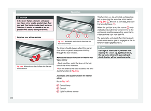 140
140 141
141 142
142 143
143 144
144 145
145 146
146 147
147 148
148 149
149 150
150 151
151 152
152 153
153 154
154 155
155 156
156 157
157 158
158 159
159 160
160 161
161 162
162 163
163 164
164 165
165 166
166 167
167 168
168 169
169 170
170 171
171 172
172 173
173 174
174 175
175 176
176 177
177 178
178 179
179 180
180 181
181 182
182 183
183 184
184 185
185 186
186 187
187 188
188 189
189 190
190 191
191 192
192 193
193 194
194 195
195 196
196 197
197 198
198 199
199 200
200 201
201 202
202 203
203 204
204 205
205 206
206 207
207 208
208 209
209 210
210 211
211 212
212 213
213 214
214 215
215 216
216 217
217 218
218 219
219 220
220 221
221 222
222 223
223 224
224 225
225 226
226 227
227 228
228 229
229 230
230 231
231 232
232 233
233 234
234 235
235 236
236 237
237 238
238 239
239 240
240 241
241 242
242 243
243 244
244 245
245 246
246 247
247 248
248 249
249 250
250 251
251 252
252 253
253 254
254 255
255 256
256 257
257 258
258 259
259 260
260 261
261 262
262 263
263 264
264 265
265 266
266 267
267 268
268 269
269 270
270 271
271 272
272 273
273 274
274 275
275 276
276 277
277 278
278 279
279 280
280 281
281 282
282 283
283 284
284 285
285 286
286 287
287 288
288 289
289 290
290 291
291 292
292 293
293 294
294 295
295 296
296 297
297 298
298 299
299 300
300 301
301 302
302 303
303 304
304 305
305 306
306 307
307 308
308 309
309 310
310 311
311 312
312 313
313 314
314 315
315 316
316 317
317 318
318 319
319