Page 217 of 536
2WD Indicator Light — If Equipped
Yellow Telltale
Light What It Means
2WD Indicator Light
This light alerts the driver that the vehicle is in the two-wheel drive mode.
Green Telltale Indicator Lights
Park/Headlight On Indicator Light
Green Telltale
Light What It Means
Park/Headlight On Indicator Light
This indicator will illuminate when the park lights or headlights are turned on.
Front Fog Indicator Light — If Equipped
Green Telltale
Light What It Means
Front Fog Indicator Light — If Equipped
This indicator will illuminate when the front fog lights are on. 4UNDERSTANDING YOUR INSTRUMENT PANEL 215
Page 220 of 536

Cruise Control SET Indicator Light — If Equipped
White Telltale
Light What It Means
Cruise Control SET Indicator Light
This light will turn on when the speed control is set. Refer to “Speed Control” in “Understanding
The Features Of Your Vehicle” for further information.
INSTRUMENT CLUSTER DISPLAY
Your vehicle may be equipped with an instrument cluster
display, which offers useful information to the driver. With
the ignition in the STOP/OFF position, opening/closing of
a door will activate the display for viewing, and display
the total miles (kilometers) in the odometer. Your instru-
ment cluster display is designed to display important
information about your vehicle’s systems and features.
Using a driver interactive display located on the instru-
ment panel, your instrument cluster display can show you
how systems are working and give you warnings when
they aren’t. The steering wheel mounted controls allow
you to scroll through and enter the main menus and
submenus. You can access the specific information you
want and make selections and adjustments. Instrument Cluster Display Controls
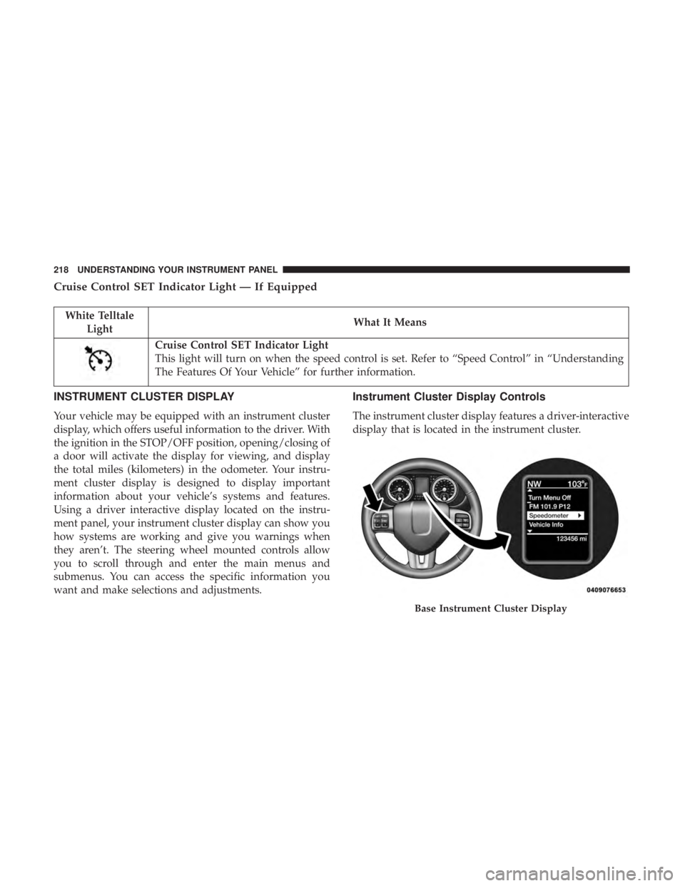
The instrument cluster display features a driver-interactive
display that is located in the instrument cluster.
Base Instrument Cluster Display218 UNDERSTANDING YOUR INSTRUMENT PANEL
Page 222 of 536
The system allows the driver to select information by
pushing the following instrument cluster display control
buttons located on the left side of the steering wheel:
• Up Arrow Button
Push and release the up arrow button to scroll
upward through the main menu items, submenu
screen, and vehicle settings. • Down Arrow Button
Push and release the down arrow button to scroll
downward through the main menu items, sub-
menu screen, and vehicle settings.
• Right Arrow Button
Push and release the right arrow button to
access/select the information screens or sub-
menu screens of a main menu item. Push and
hold the RIGHT arrow button for two seconds to
reset displayed/selected features that can be reset.
• Left Arrow Button
Push and release the left arrow button to access/
select the information screens, submenu screens
of a main menu item, or to return to the main
menu.Instrument Cluster Display Control Buttons220 UNDERSTANDING YOUR INSTRUMENT PANEL
Page 225 of 536

messages of this type are then stored (as long as the
condition that activated it remains active) and can be
reviewed from the “Messages” main menu item. As long as
there is a stored message, an “i” will be displayed in the
instrument cluster display’s compass/outside temp line.
Examples of this message type are “Right Front Turn Signal
Lamp Out” and “Low Tire Pressure.”
• Unstored Messages
This message type is displayed indefinitely or until the
condition that activated the message is cleared. Examples
of this message type are “Turn Signal On” (if a turn signal
is left on) and “Lights On” (if driver leaves the vehicle).
• Unstored Messages Until RUN
These messages deal primarily with the Remote Start
feature. This message type is displayed until the ignition is
in the RUN state. Examples of this message type are
“Remote Start Aborted - Door Ajar” and “Press Brake
Pedal and Push Button to Start.”
• Five Second Unstored Messages
When the appropriate conditions occur, this type of mes-
sage takes control of the main display area for five seconds
and then returns to the previous screen. An example of this
message type is “Automatic High Beams On.” Oil Life Reset
Your vehicle is equipped with an engine oil change indi-
cator system. The “Oil Change Required” message will
display in the instrument cluster display after a single
chime has sounded, to indicate the next scheduled oil
change interval. The engine oil change indicator system is
duty cycle based, which means the engine oil change
interval may fluctuate, dependent upon your personal
driving style.
NOTE: Use the steering wheel instrument cluster display
controls for the following procedure(s).
Vehicles Equipped With Passive Entry
1. Without pushing the brake pedal, push the ENGINE
START/STOP button and place the ignition to the
ON/RUN position (do not start the engine).
2. Push and release the down arrow button to scroll
downward through the main menu to “Vehicle Info.”
3. Push and release the right arrow button to access the
”Vehicle Info” screen, then scroll up or down to select
“Oil Life.”
4. Push and hold the right arrow button to select “Reset”. 4UNDERSTANDING YOUR INSTRUMENT PANEL 223
Page 230 of 536
Setting Names Setting Names Abbreviated
(Left Submenu Layer) Sub-Menus
(Right Submenu Layer)
13 Auto Lock Doors Auto Lock Doors On; Off
14 Auto Unlock Doors Auto Unlock Doors On; Off
15 Sound Horn with Remote Start Horn w/ Rmt Start On; Off
16 Sound Horn with Remote Lock Horn w/ Rmt Lock On; Off
17 Remote Unlock Sequence Remote Unlock Driver Door; All Doors
18 Key Fob Linked to Memory Key in Memory On; Off
19 Passive Entry Passive Entry On; Off
20 Remote Start Comfort System Rmt Start Comfort On; Off
21 Easy Exit Seat Easy Exit Seat On; Off
22 Key-off Power Delay Power Off Delay Off; 45 seconds; 5 minutes;
10 minutes
23 Commercial Settings Commercial • Aux Switches
• Power Take-Off
• PIN Setup
• ParkSense Setup
24 Aero Ride Height Mode Aero Mode On; Off
25 Tire/Jack Mode Tire/Jack Mode On; Off
26 Transport Mode Transport Mode On; Off
27 Wheel Alignment Mode Wheel Alignment On; Off228 UNDERSTANDING YOUR INSTRUMENT PANEL
Page 231 of 536
Setting Names Setting Names Abbreviated
(Left Submenu Layer) Sub-Menus
(Right Submenu Layer)
28 Horn w/ Remote Lower Horn w/ Rmt Lwr On; Off
29 Lights w/ Remote Lower Lights w/ Rmt Lwr On; Off
30 Trailer Select Trailer Select Trailer 1; Trailer 2; Trailer 3;
Trailer 4
31 Brake Type Brake Type Light Electric; Heavy Electric;
Light EOH; Heavy EOH
32 Trailer Name Trailer Name • Trailer # (# is equal to slot
position)
• Boat
• Car
• Cargo
• Dump
• Equipment
• Flatbed
• Gooseneck
• Horse
• Ta g
• Motorcycle
• Snowmobile
• Travel
• Utility
• 5th Wheel 4UNDERSTANDING YOUR INSTRUMENT PANEL 229
Page 235 of 536

The electrical loads that may be switched off (if equipped),
and vehicle functions which can be affected by load
reduction:
• Heated Seat/Vented Seats/Heated Wheel
• Heated/Cooled Cup Holders — If Equipped
• Rear Defroster And Heated Mirrors
• HVAC System
• 115V AC Power Inverter System
• Audio and Telematics System
Loss of the battery charge may indicate one or more of the
following conditions:
• The charging system cannot deliver enough electrical
power to the vehicle system because the electrical loads
are larger than the capability of charging system. The
charging system is still functioning properly.
• Turning on all possible vehicle electrical loads (e.g.
HVAC to max settings, exterior and interior lights,
overloaded power outlets +12V, 115V AC, USB ports)
during certain driving conditions (city driving, towing,
frequent stopping). • Installing options like additional lights, upfitter electri-
cal accessories, audio systems, alarms and similar de-
vices.
• Unusual driving cycles (short trips separated by long
parking periods).
• The vehicle was parked for an extended period of time
(weeks, months).
• The battery was recently replaced and was not charged
completely.
• The battery was discharged by an electrical load left on
when the vehicle was parked.
• The battery was used for an extended period with the
engine not running to supply radio, lights, chargers,
+12V portable appliances like vacuum cleaners, game
consoles and similar devices. 4UNDERSTANDING YOUR INSTRUMENT PANEL 233
Page 248 of 536
Auto Comfort Systems — If Equipped
After pressing the “Auto-On Comfort” button on the
touchscreen, the following settings will be available:
Setting Name Selectable Options
Auto-On Driver Heated/Ventilated
Seat & Steering Wheel With Vehicle
Start — If Equipped On Off
NOTE: When the “Auto-On Driver Heated/Ventilated Seat & Steering Wheel With Vehicle Start” feature is selected
the driver’s heated seat and heated steering wheel will automatically turn on when temperatures are below 40° F
(4.4° C). When temperatures are above 80° F (26.7° C) the driver vented seat will turn on. 246 UNDERSTANDING YOUR INSTRUMENT PANEL