Page 281 of 536

Icon Description
Front Defrost Setting
Turn the Mode Control knob to the Defrost mode. Air comes from the windshield and side win-
dow demist outlets. When the defrost setting is selected, the blower level will increase. Use De-
frost mode with maximum temperature settings for best windshield and side window defrosting
and defogging.
Rear Defrost Button
Push and release the Rear Defrost Control button to turn on the rear window defroster and the
heated outside mirrors (if equipped). An indicator will illuminate when the rear window de-
froster is on. The rear window defroster automatically turns off after 10 minutes.
Temperature Control
Use this control knob to regulate the temperature of the air inside the passenger compartment. Rotat-
ing the knob counterclockwise, from top center into the blue area of the scale, indicates cooler tem-
peratures. Rotating the knob clockwise, into the red area, indicates warmer temperatures.
Blower Control
There are seven blower speeds. Use this control knob to regulate the amount of air forced
through the system in any mode you select. The blower speed increases as you move the con-
trol clockwise from the off position.
NOTE: Depending on the configuration, your vehicle may be equipped with four blower
speeds. 4UNDERSTANDING YOUR INSTRUMENT PANEL 279
Page 288 of 536

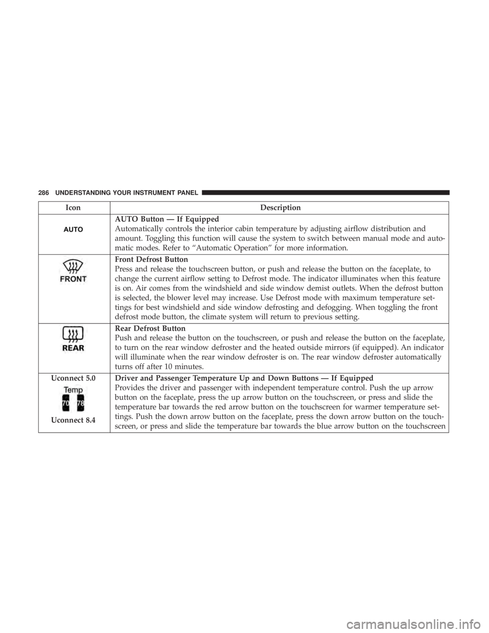
Icon Description
AUTO Button — If Equipped
Automatically controls the interior cabin temperature by adjusting airflow distribution and
amount. Toggling this function will cause the system to switch between manual mode and auto-
matic modes. Refer to “Automatic Operation” for more information.
Front Defrost Button
Press and release the touchscreen button, or push and release the button on the faceplate, to
change the current airflow setting to Defrost mode. The indicator illuminates when this feature
is on. Air comes from the windshield and side window demist outlets. When the defrost button
is selected, the blower level may increase. Use Defrost mode with maximum temperature set-
tings for best windshield and side window defrosting and defogging. When toggling the front
defrost mode button, the climate system will return to previous setting.
Rear Defrost Button
Push and release the button on the touchscreen, or push and release the button on the faceplate,
to turn on the rear window defroster and the heated outside mirrors (if equipped). An indicator
will illuminate when the rear window defroster is on. The rear window defroster automatically
turns off after 10 minutes.
Uconnect 5.0
Uconnect 8.4 Driver and Passenger Temperature Up and Down Buttons — If Equipped
Provides the driver and passenger with independent temperature control. Push the up arrow
button on the faceplate, press the up arrow button on the touchscreen, or press and slide the
temperature bar towards the red arrow button on the touchscreen for warmer temperature set-
tings. Push the down arrow button on the faceplate, press the down arrow button on the touch-
screen, or press and slide the temperature bar towards the blue arrow button on the touchscreen286 UNDERSTANDING YOUR INSTRUMENT PANEL
Page 302 of 536
Media
Uconnect offers connections via USB, Bluetooth and auxil-
iary ports (If Equipped). Voice operation is only available
for connected USB and iPod devices. (Remote CD player
optional and not available on all vehicles.)
Push the VR button . After the beep, say one of the
following commands and follow the prompts to switch
your media source or choose an artist.
• Change source to Bluetooth
• Change source to iPod
• Change source to USB
• Play artist Beethoven; Play album Greatest Hits; Play
song Moonlight Sonata; Play genre Classical TIP: For the Uconnect 3.0, Uconnect 5.0 and 8.4/8.4 NAV
systems, select Browse to see all of the music on your iPod
or USB device. Your Voice Command must match exactly
how the artist, album, song and genre information is
displayed.
Uconnect 3.0 Media300 UNDERSTANDING YOUR INSTRUMENT PANEL
Page 306 of 536

Voice Text Reply
Uconnect will announce incoming text messages. Push the
Phone button and say Listen. (Must have compatible
mobile phone paired to Uconnect system.)
1. Once an incoming text message is read to you, push the
Phone button . After the beep, say: “Reply.”
2. Listen to the Uconnect prompts. After the beep, repeat
one of the pre-defined messages and follow the system
prompts.
PRE-DEFINED VOICE TEXT REPLY RESPONSES
Yes. Stuck in traffic. See you later.
No. Start without
me. I’ll be late.
Okay. Where are you?
I will be
minutes late.Call me. Are you there
yet?
I’ll call you later. I need
directions. See you in
of
minutes.
I’m on my way.
Can’t talk right
now.
I’m lost. Thanks. TIP: Your mobile phone must have the full implementation
of the Message Access Profile (MAP) to take advantage of
this feature. For details about MAP, visit
UconnectPhone.com.
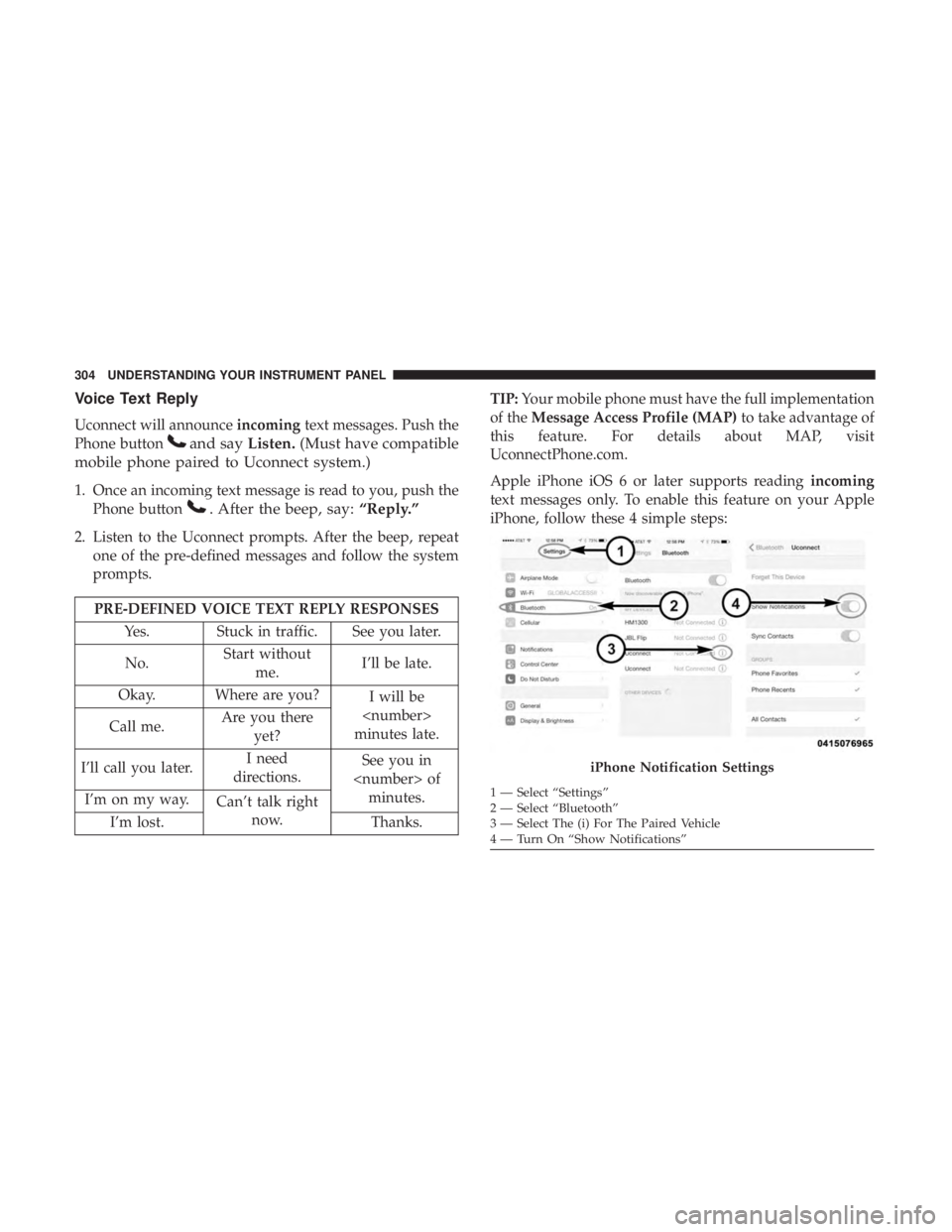
Apple iPhone iOS 6 or later supports reading incoming
text messages only. To enable this feature on your Apple
iPhone, follow these 4 simple steps:
iPhone Notification Settings1 — Select “Settings”
2 — Select “Bluetooth”
3 — Select The (i) For The Paired Vehicle
4 — Turn On “Show Notifications”304 UNDERSTANDING YOUR INSTRUMENT PANEL
Page 311 of 536
You must be registered with Uconnect Access and have a
compatible MAP – enabled smartphone to use your voice
to send a personalized text message. For details about
MAP, visit UconnectPhone.com.
Apple iPhone iOS6 or later supports reading incoming text
messages only. To enable this feature on your Apple
iPhone, follow these 4 simple steps: TIP:
• Voice Texting is not compatible with iPhone, but if your
vehicle is equipped with Siri Eyes Free, you can use your
voice to send a text message.
• Messages are limited to 140 characters.
• The Messaging button on the touchscreen must be
illuminated to use the feature.
iPhone Notification Settings1 — Select “Settings”
2 — Select “Bluetooth”
3 — Select The (i) For The Paired Vehicle
4 — Turn On “Show Notifications” 4UNDERSTANDING YOUR INSTRUMENT PANEL 309
Page 316 of 536

Do Not Disturb
With Do Not Disturb, you can disable notifications from
incoming calls and texts, allowing you to keep your eyes
on the road and hands on the wheel. For your convenience,
there is a counter display to keep track of your missed calls
and text messages while you were using Do Not Disturb.
Do Not Disturb can automatically reply with a text mes-
sage, a call or both, when declining an incoming call and
send it to voicemail.
Automatic reply messages can be:
• “I am driving right now, I will get back to you shortly.”
• Create a custom auto reply message up to 160 characters.
NOTE: Only the first 25 characters can been seen on the
touchscreen while typing a custom message.
While in Do Not Disturb, Conference Call can be selected
so you can still place a second call without being inter-
rupted by incoming calls.
NOTE:
• Reply with text message is not compatible with iPhones.
• Auto reply with text message is only available on
phones that support Bluetooth MAP. General Information
This device complies with FCC rules Part 15 and Industry
Canada RSS-210. Operation is subject to the following two
conditions:
1. This device may not cause harmful interference.
2. This device must accept any interference that may be
received including interference that may cause unde-
sired operation.
NOTE:
• The transmitter has been tested and it complies with
FCC and IC rules. Changes or modifications not ex-
pressly approved by the party responsible for compli-
ance could void the user ’s authority to operate the
device.
• The term IC before the certification/registration number
only signifies that Industry Canada technical specifica-
tions were met.314 UNDERSTANDING YOUR INSTRUMENT PANEL
Page 489 of 536
Power Distribution Center
The Power Distribution Center is located in the engine
compartment near the battery. This center contains car-
tridge fuses, micro fuses, relays, and circuit breakers. A
description of each fuse and component may be stamped
on the inside cover, otherwise the cavity number of each
fuse is stamped on the inside cover that corresponds to the
following chart.
Cavity Cartridge Fuse Micro Fuse Description
F01 80 Amp Black – Rad Fan Control Module – If Equipped
F03 60 Amp Yellow – Rad Fan – If Equipped
F05 40 Amp Green – Compressor for Air Suspension – If Equipped
F06 40 Amp Green – Antilock Brakes/Electronic Stability Control
Pump
F07 40 Amp Green – Starter Solenoid
F08 20 Amp Blue (1500 LD/
Cummins Diesel) – Emissions Diesel – If EquippedPower Distribution Center Location
7MAINTAINING YOUR VEHICLE 487
Page 490 of 536
Cavity Cartridge Fuse Micro Fuse Description
F09 40 Amp Green
(Special Services
Vehicle & Cummins
Diesel) – Diesel Fuel Heater – If Equipped
F10 40 Amp Green – Body Controller / Exterior Lighting #2
F10 50 Amp Red – Body Controller / Exterior Lighting #2 –
If Equipped with Stop/Start
F11 30 Amp Pink – Integrated Trailer Brake Module – If Equipped
F12 40 Amp Green – Body Controller #3 / Power Locks
F13 40 Amp Green – Blower Motor
F14 40 Amp Green – Body Controller #4 / Interior Lighting
F16 30 Amp Pink – Smart Bar – If Equipped
F19 20 Amp Blue
(1500 LD Diesel)
30 Amp Pink
(Cummins Diesel) – SCR – If Equipped
F20 30 Amp Pink – Passenger Door Module
F21 30 Amp Pink – Drive Train Control Module
F22 20 Amp Blue
30 Amp Pink
(Cummins Diesel) – Engine Control Module488 MAINTAINING YOUR VEHICLE