Page 144 of 542

HEATED STEERING WHEEL — IF EQUIPPED
The steering wheel contains a heating element that helps
warm your hands in cold weather. The heated steering
wheel has only one temperature setting. Once the heated
steering wheel has been turned on, it will operate for an
average of 80 minutes before automatically shutting off.
This time may vary based on the temperature of the
surrounding environment or the heated steering wheel
may not turn on when it is already warm.
The heated steering wheel control button is located on the
center of the instrument panel below the climate controls.
If your vehicle is equipped with a touchscreen, the heated
steering wheel control button is located within the climate
or controls screen of the touchscreen.
•Press the heated steering wheel button
once to turn
the heating element on.
• Press the heated steering wheel buttona second time
to turn the heating element off.
NOTE: The engine must be running for the heated steering
wheel to operate. Vehicles Equipped With Remote Start
On models that are equipped with remote start, the heated
steering wheel can be programmed to come on during a
remote start.
If your vehicle is equipped with a touchscreen, this feature
can be programmed through the Uconnect system. Refer to
“Uconnect Settings” in “Understanding Your Instrument
Panel” for further information.
If your vehicle is not equipped with a touchscreen, this
feature can be programmed through the instrument cluster
display. Refer to “Instrument Cluster Display” in “Under-
standing Your Instrument Panel” for further information.
WARNING!
•
Persons who are unable to feel pain to the skin
because of advanced age, chronic illness, diabetes,
spinal cord injury, medication, alcohol use, exhaus-
tion, or other physical conditions must exercise care
when using the steering wheel heater. It may cause
burns even at low temperatures, especially if used
for long periods.
(Continued)
142 UNDERSTANDING THE FEATURES OF YOUR VEHICLE
Page 145 of 542
WARNING!(Continued)
•Do not place anything on the steering wheel that
insulates against heat, such as a blanket or steering
wheel covers of any type and material. This may
cause the steering wheel heater to overheat.
SPEED CONTROL
When engaged, the Speed Control takes over accelerator
operations at speeds greater than 25 mph (40 km/h).
The Speed Control buttons are located on the right side of
the steering wheel.
NOTE:In order to ensure proper operation, the Speed
Control System has been designed to shut down if multiple
speed control functions are operated at the same time. If
this occurs, the Speed Control System can be reactivated by
pushing the Speed Control ON/OFF button and resetting
the desired vehicle set speed.
Speed Control Switches
1 — ON/OFF 3 — SET -
2 — RES + 4 — CANCEL
3
UNDERSTANDING THE FEATURES OF YOUR VEHICLE 143
Page 164 of 542

When enabled, active guide lines are overlaid on the image
to illustrate the width of the vehicle and its projected
backup path based on the steering wheel position. The
active guide lines will show separate zones that will help
indicate the distance to the rear of the vehicle.
NOTE:For further information about how to access and
change the programmable features of the ParkView Rear
Backup Camera, refer to “Uconnect Settings” in “Under-
standing Your Instrument Panel” for further information.
The following table shows the approximate distances for
each zone:
Zones Distance to the rear of
the vehicle
Red 0 - 1 ft (0 - 30 cm)
Yellow 1 ft - 6.5 ft (30 cm - 2m)
Green 6.5 ft or greater (2 m or
greater)
WARNING!
Drivers must be careful when backing up even when
using the ParkView Rear Back Up Camera. Always
check carefully behind your vehicle, and be sure to
check for pedestrians, animals, other vehicles, obstruc-
tions, or blind spots before backing up. You are re-
sponsible for the safety of your surroundings and must
continue to pay attention while backing up. Failure to
do so can result in serious injury or death.
CAUTION!
•To avoid vehicle damage, ParkView should only be
used as a parking aid. The ParkView camera is
unable to view every obstacle or object in your drive
path.
• To avoid vehicle damage, the vehicle must be driven
slowly when using ParkView to be able to stop in
time when an obstacle is seen. It is recommended
that the driver look frequently over his/her shoulder
when using ParkView.
NOTE: If snow, ice, mud, or any foreign substance builds
up on the camera lens, clean the lens, rinse with water, and
dry with a soft cloth. Do not cover the lens.
162 UNDERSTANDING THE FEATURES OF YOUR VEHICLE
Page 195 of 542

UNDERSTANDING YOUR INSTRUMENT PANEL
CONTENTS
�INSTRUMENT PANEL FEATURES ...........195
� INSTRUMENT CLUSTER ..................196
� WARNING AND INDICATOR LIGHTS ........200
▫ Red Telltale Indicator Lights ...............201
▫ Yellow Telltale Indicator Lights .............208
▫ Green Telltale Indicator Lights ..............219
▫ Blue Telltale Indicator Lights ...............221
▫ White Telltale Indicator Lights ..............222
� INSTRUMENT CLUSTER DISPLAY ...........223
▫ Instrument Cluster Display Controls .........223
▫ Instrument Cluster Display Screens ..........225
▫ Oil Life Reset ......................... .227
▫ Instrument Cluster Display Selectable Menu
Items .............................. .228▫
Instrument Cluster Display Messages .........235
▫ Battery Saver On/Battery Saver Mode Message —
Electrical Load Reduction Actions —
If Equipped ......................... .237
� CYBERSECURITY ....................... .239
� UCONNECT SETTINGS ...................240
▫ Buttons On The Faceplate .................241
▫ Buttons On The Touchscreen ...............242
▫ Customer Programmable Features —
Uconnect 5.0 Personal Settings ..............242
▫ Customer Programmable Features —
Uconnect 8.4/8.4 NAV Personal Settings ......259
� UCONNECT RADIOS — IF EQUIPPED ........276
� IPOD/USB/MP3 CONTROL — IF EQUIPPED . . . .276
� STEERING WHEEL AUDIO CONTROLS — IF
EQUIPPED ........................... .2774
Page 208 of 542
Electric Power Steering Fail Warning Light — If Equipped
Red TelltaleLight What It Means
Electric Power Steering Fail Warning — If Equipped
This light is used to manage the electrical warning of the EPS (Electric Power Steering). Refer to
“Electric Power Steering” in “Starting And Operating” for further information.
Trailer Brake Disconnected Warning Light
Red Warning
Light What It Means
Trailer Brake Disconnected Warning Light
This telltale is on when the Trailer Brake has been disconnected.
206 UNDERSTANDING YOUR INSTRUMENT PANEL
Page 214 of 542

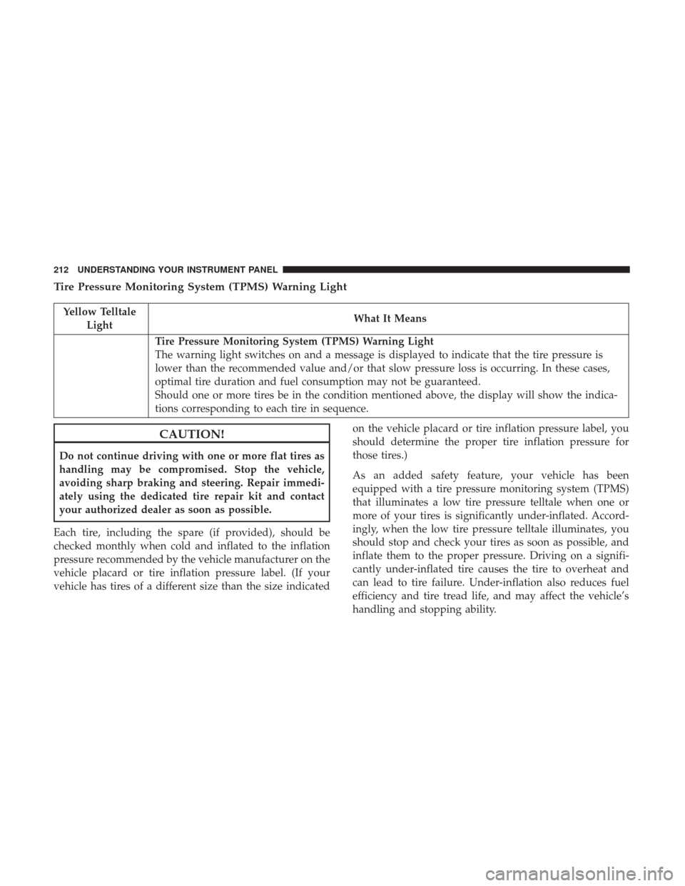
Tire Pressure Monitoring System (TPMS) Warning Light
Yellow TelltaleLight What It Means
Tire Pressure Monitoring System (TPMS) Warning Light
The warning light switches on and a message is displayed to indicate that the tire pressure is
lower than the recommended value and/or that slow pressure loss is occurring. In these cases,
optimal tire duration and fuel consumption may not be guaranteed.
Should one or more tires be in the condition mentioned above, the display will show the indica-
tions corresponding to each tire in sequence.
CAUTION!
Do not continue driving with one or more flat tires as
handling may be compromised. Stop the vehicle,
avoiding sharp braking and steering. Repair immedi-
ately using the dedicated tire repair kit and contact
your authorized dealer as soon as possible.
Each tire, including the spare (if provided), should be
checked monthly when cold and inflated to the inflation
pressure recommended by the vehicle manufacturer on the
vehicle placard or tire inflation pressure label. (If your
vehicle has tires of a different size than the size indicated on the vehicle placard or tire inflation pressure label, you
should determine the proper tire inflation pressure for
those tires.)
As an added safety feature, your vehicle has been
equipped with a tire pressure monitoring system (TPMS)
that illuminates a low tire pressure telltale when one or
more of your tires is significantly under-inflated. Accord-
ingly, when the low tire pressure telltale illuminates, you
should stop and check your tires as soon as possible, and
inflate them to the proper pressure. Driving on a signifi-
cantly under-inflated tire causes the tire to overheat and
can lead to tire failure. Under-inflation also reduces fuel
efficiency and tire tread life, and may affect the vehicle’s
handling and stopping ability.
212 UNDERSTANDING YOUR INSTRUMENT PANEL
Page 225 of 542

INSTRUMENT CLUSTER DISPLAY
Your vehicle may be equipped with an instrument cluster
display, which offers useful information to the driver. With
the ignition in the STOP/OFF position, opening/closing of
a door will activate the display for viewing, and display
the total miles (kilometers) in the odometer. Your instru-
ment cluster display is designed to display important
information about your vehicle’s systems and features.
Using a driver interactive display located on the instru-
ment panel, your instrument cluster display can show you
how systems are working and give you warnings when
they aren’t. The steering wheel mounted controls allow
you to scroll through and enter the main menus and
submenus. You can access the specific information you
want and make selections and adjustments.
Instrument Cluster Display Controls
The instrument cluster display features a driver-interactive
display that is located in the instrument cluster.
Base Instrument Cluster Display
4
UNDERSTANDING YOUR INSTRUMENT PANEL 223
Page 226 of 542
The instrument cluster display menu items may consist of
the following:
•Speedometer
• Vehicle Info
• Fuel Economy Info
• Trip A
• Trip B
• Audio •
Trailer Tow
• Stored Messages
• Screen Setup
• Vehicle Settings (Not Equipped with a Uconnect 5.0 &
8.4 radio)
The system allows the driver to select information by
pushing the following instrument cluster display control
buttons located on the left side of the steering wheel:
Premium Instrument Cluster Display
Instrument Cluster Display Control Buttons
224 UNDERSTANDING YOUR INSTRUMENT PANEL