2017 PEUGEOT 4008 bulb
[x] Cancel search: bulbPage 5 of 368

.
4008_en_Chap00a_sommaire_ed01-2016
general safety recommendations 141
Direction indicators
1
42
Hazard warning lamps
1
42
Hor n
14
2
Braking assistance systems
1
43
tr
ajectory control systems
1
45
Front seat belts
1
47
Airbags
151
Child seats
1
56
Deactivating the passenger's front airbag
1
58
ISOFIX child seats
1
65
Child lock
1
71
Fuel tank
1
73
Snow chains
1
75
Automatic power cut-off to accessories
176
Changing a wiper blade
1
76
to
wing a trailer
1
77
Fitting roof bars
1
79
Bonnet
180
Petrol engines
1
81
Diesel engines
1
82
Checking levels
1
83
Checks
18
6te mporary puncture
repair kit 1 89
Changing a wheel
1
93
Changing a bulb
1
99
Changing a fuse
2
05
12 V battery
2
11
to
wing the vehicle
2
15
Running out of fuel (Diesel)
2
18
Petrol engines
2
19
Petrol weights
2
20
Diesel engines
2
25
Diesel weights
2
26
Dimensions
231
Identification markings
2
33Bluetooth® telephone with voice
recognition 23 5
to
uch screen A
uD
IO -
t
e
LeM
A
tI
C system
2
47
tOuC
H SCR
e
e
N AuD
IO - CD system
2
89
A
uD
IO - CD system
3
13
Safety
Practical information In the event of a breakdown
te
chnical dataAudio equipment and telematics
Alphabetical index
Contents
Page 6 of 368

4
4008_en_Chap00b_vue-ensemble_ed01-2016
exterior
Lighting controls 127-131
Headlamp beam adjustment 1 33
Welcome lighting
1
32
Changing bulbs
1
99-202
-
f
ront lamps
-
f
ront foglamps
-
d
irection indicator repeaters
W iper c ontrols
13
4 -137
Changing a wiper b l a d e
17
6
Door mirrors
7
6 -77
Doors
6
2, 64
-
ope
ning / closing
-
c
entral locking
Child lock
1
71
el
ectric windows
6
8 - 69
Alarm
65-67
Panoramic sunroof
7
0
Roof bars
1
79
Braking assistance
1
43-144
tra
jectory control
1
45-146
ty
re pressures
1
93, 233
un
der-inflation detection
1
14-117
Boot
63
-
ope
ning / closing
-
em
ergency release
te
mporary puncture
repair kit
1
89-192
Changing a wheel
1
93-198
-
tools
-
r
emoving / refitting
Snow chains
1
75
Changing bulbs
2
03-204
-
r
ear lamps
-
3rd brake lamp
-
n
umber plate lamps
-
foglamp
Parking sensors
1
23-125
Reversing camera
1
26
to
w b a r
17 7-178
to
wing
215 -217
Fuel tank
1
73
Remote control key /
electronic key
5
2-61
-
ope
ning / closing
-
a
nti-theft protection
-
battery
Over view
Page 11 of 368

9
4008_en_Chap00b_vue-ensemble_ed01-2016
Maintenance - technical data
engine compartment
fuses 2 05, 208 -210
Running out of fuel, Diesel
2
18
Checking levels
18
3 -185
-
oil
-
b
rake fluid
-
coolant
-
s
creenwash/headlamp wash fluid
Changing bulbs
1
99-204
-
front
-
rear Petrol engines
2
19
Petrol weights
2
20 -225
Diesel engines
2
26
Diesel weights
2
27-230
Dimensions
231
Off-road performance
2
32
Identification markings
2
33
Bonnet
180
Petrol engine compartment
1
81
Diesel engine compartment
1
82 Batter y
211-214
Automatic power cut-off to accessories
176
Checking components
1
86-188
-
b
attery electrolyte
-
a
ir filter
-
o
il filter
-
p
article filter (Diesel)
-
b
rake pads / discs
.
Over view
Page 18 of 368

16
Operation indicator lamps
If one of the following indicator lamps comes on, this confirms that the corresponding system has come into operation.
It may be accompanied by an audible signal and a message in the instrument panel screen.Warning /indicator lampis on Cause Action / Observations
Left-hand
direction
indicator flashing with audible
warning.
th
e lighting stalk has been pressed
downwards. If this indicator lamp flashes abnormally quickly, this
could indicate that the bulb of one of the direction
indicators has blown. Change the bulb or contact a
P
e
uge
Ot
dealer or a qualified workshop.
Right-hand
direction
indicator flashing with audible
warning.
th
e lighting stalk has been pushed
upwards. If this indicator lamp flashes abnormally quickly, this
could indicate that the bulb of one of the direction
indicators has blown. Change the bulb or contact a
P
e
uge
Ot
dealer or a qualified workshop.
Sidelamps or
dipped beam
headlamps fixed.
th
e sidelamps or dipped beam
headlamps are on.
Main beam
headlamps fixed.
th
e lighting stalk is pulled towards
you. Pull the stalk to return to dipped beam headlamps.
Front foglamps fixed.
th
e front foglamps are switched on
using the ring on the lighting control
stalk.
tu
rn the ring on the lighting control stalk rear ward
once to switch off the front foglamps.
Rear foglamp sfixed.
th
e rear foglamps are switched on.
tu
rn the ring on the stalk rear ward to switch off the
rear foglamps.
Instruments
Page 135 of 368

133
4008_en_Chap05_Eclairage-et-visibilite_ed01-2016
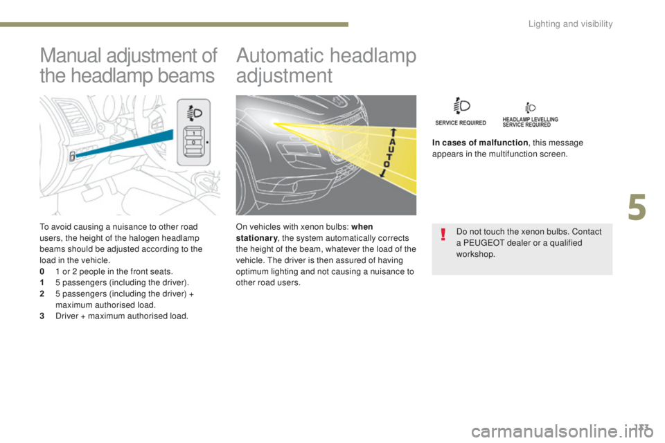
to avoid causing a nuisance to other road
users, the height of the halogen headlamp
beams should be adjusted according to the
load in the vehicle.
0
1 o
r 2 people in the front seats.
1
5
passengers (including the driver).
2
5
passengers (including the driver) +
maximum authorised load.
3
D
river + maximum authorised load.
Manual adjustment of
the headlamp beams Automatic headlamp
adjustment
In cases of malfunction
, this message
appears in the multifunction screen.
Do not touch the xenon bulbs. Contact
a P
e
uge
Ot
dealer or a qualified
workshop.
On vehicles with xenon bulbs: when
stationary
, the system automatically corrects
the height of the beam, whatever the load of the
vehicle.
t
h
e driver is then assured of having
optimum lighting and not causing a nuisance to
other road users.
5
Lighting and visibility
Page 143 of 368

141
4008_en_Chap06_securite_ed01-2016
general safety recommendations
Depending on the legislation in force in
the country, certain safety equipment
may be compulsory: high visibility
safety vests, warning triangles,
breathalysers, spare bulbs, spare fuses,
fire extinguisher, first aid kit, mud flaps
at the rear of the vehicle...
Labels are applied at various
points on your vehicle.
t
h
ey carry
safety warnings as well as vehicle
identification information. Do not
remove them: they form an integral part
of your vehicle.
For any work on your vehicle, use
a qualified workshop that has the
technical information, skills and
equipment required, all of which a
P
e
uge
Ot d
ealer is able to provide.
We draw your attention to
the following points:
- the fitting of electrical equipment
or accessories not listed by
P
e
uge
Ot
may cause excessive
current consumption and faults and
failures with the electrical system of
your vehicle. Contact a P
e
uge
Ot
dealer for information on the range
of recommended accessories.
-
A
s a safety measure, access to
the diagnostic socket, used for
the vehicle's electronic systems,
is reserved strictly for P
e
uge
Ot
dealers or qualified workshops,
equipped with the special tools
required (risk of malfunctions of the
vehicle's electronic systems that
could cause breakdowns or serious
accidents).
t
he
manufacturer cannot
be held responsible if this advice is
not followed.
-
A
ny modification or adaptation
not intended or authorised by
Automobiles P
e
uge
Ot
or
carried out without meeting the
technical requirements defined
by the manufacturer would lead
to the suspension of the legal and
contractual warranties.
Installation of accessory
radio communication
transmitters
Before installing a radio communication
transmitter, you must contact a
P
e
uge
Ot
dealer for the specification
of transmitters which can be fitted
(frequency, maximum power,
aerial position, specific installation
requirements), in line with the Vehicle
el
ectromagnetic Compatibility
Directive
(2004/104/
eC
).
6
Safety
Page 201 of 368

199
4008_en_Chap08_en-cas-de panne_ed01-2016
Changing a bulb
For bulbs that have alignment lugs
(H1, H7...) ensure that they are
fitted correctly for the best lighting
performance.
th
e headlamps have polycarbonate
lenses with a protective coating:
F
d
o not clean them using a dr y
or abrasive cloth, nor with a
detergent or solvent product,
F
u
se a sponge and soapy water,
F
w
hen using a high pressure washer
on persistent marks, do not keep
the lance directed towards the
lamps or their edges for too long,
so as not to damage their protective
coating and seals.
F
D
o not touch the bulb directly with
your fingers, use lint-free cloths.
Changing a bulb should only be done
after the headlamp has been switched
off for several minutes (risk of serious
burns).
It is imperative to use only anti-
ultraviolet (
uV
) type bulbs in order not
to damage the headlamp.
Always replace a failed bulb with a
new bulb with the same type and
specification.
Risk of electrocution
Replacement of the xenon bulbs
(D1S-35W) must be carried out by
a P
e
uge
Ot
dealer or a qualified
workshop.
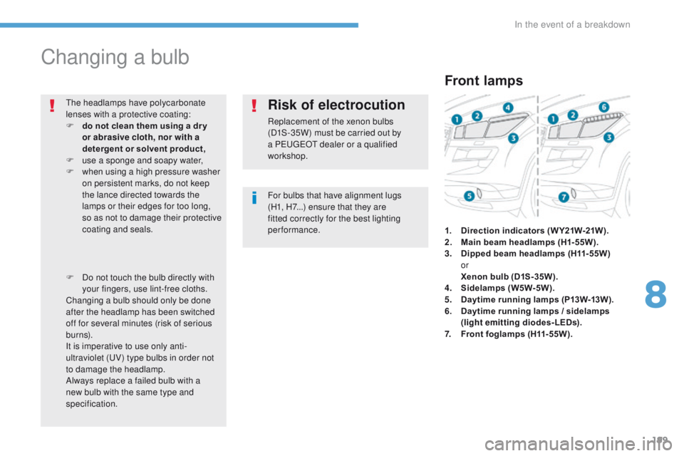
Front lamps
1. Direction indicators ( W Y21W-21W ).
2. M ain beam headlamps (H1-55W).
3.
D
ipped beam headlamps (H11-55W)
or
Xe
non bulb (D1S-35W).
4.
S
idelamps (W5W-5W).
5.
D
aytime running lamps (P13W-13W).
6.
D
aytime running lamps / sidelamps
(light emitting diodes-LEDs).
7.
F
ront foglamps (H11-55W).
8
In the event of a breakdown
Page 202 of 368

200
4008_en_Chap08_en-cas-de panne_ed01-2016
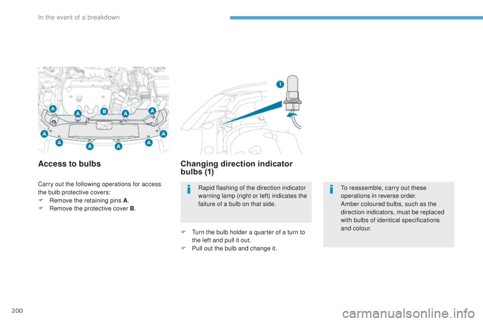
Carry out the following operations for access
the bulb protective covers:
F
R
emove the retaining pins A .
F
R
emove the protective cover B .
Access to bulbs Changing direction indicator
bulbs (1)
F turn the bulb holder a quarter of a turn to
the left and pull it out.
F
P
ull out the bulb and change it.Rapid flashing of the direction indicator
warning lamp (right or left) indicates the
failure of a bulb on that side.
to
reassemble, carry out these
operations in reverse order.
Amber coloured bulbs, such as the
direction indicators, must be replaced
with bulbs of identical specifications
and colour.
In the event of a breakdown