Page 146 of 414
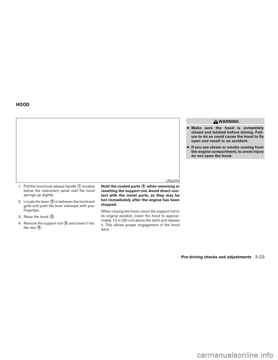
1. Pull the hood lock release handle�1located
below the instrument panel until the hood
springs up slightly.
2. Locate the lever
�2in between the hood and
grille and push the lever sideways with your
fingertips.
3. Raise the hood
�3.
4. Remove the support rod
�4and insert it into
the slot
�5. Hold the coated parts
�Awhen removing or
resetting the support rod. Avoid direct con-
tact with the metal parts, as they may be
hot immediately after the engine has been
stopped.
When closing the hood, return the support rod to
its original position, lower the hood to approxi-
mately 12 in (30 cm) above the latch and release
it. This allows proper engagement of the hood
latch.
WARNING
● Make sure the hood is completely
closed and latched before driving. Fail-
ure to do so could cause the hood to fly
open and result in an accident.
● If you see steam or smoke coming from
the engine compartment, to avoid injury
do not open the hood.
LPD2370
HOOD
Pre-driving checks and adjustments3-23
Page 147 of 414

WARNING
The rear hatch must be closed securely
before driving. An open rear hatch could
allow dangerous exhaust gases to be
drawn inside the vehicle. For additional
information, refer to “Exhaust gas (carbon
monoxide)” in the “Starting and driving”
section of this manual.
OPENING THE REAR HATCH
To open the rear hatch, unlock it with one of the
following operations, then pull the handle.● Push the power door lock switch to the
unlock position.
● Unlock all doors using the key.
● Press the
button on the key fob (if
equipped) twice. For additional information,
refer to “Remote keyless entry system (mod-
els without NISSAN Intelligent Key®)” in this
section. ●
Push the rear hatch request switch or door
handle request switch (if equipped) twice.
For additional information, refer to “NISSAN
Intelligent Key®” in this section.
● Press the
button on the Intelligent Key
(if equipped) twice. For additional informa-
tion, refer to “NISSAN Intelligent Key®” in
this section.
LPD2170
REAR HATCH
3-24Pre-driving checks and adjustments
Page 149 of 414

FUEL-FILLER CAP
WARNING
●Gasoline is extremely flammable and
highly explosive under certain condi-
tions. You could be burned or seriously
injured if it is misused or mishandled.
Always stop the engine and do not
smoke or allow open flames or sparks
near the vehicle when refueling.
● Do not attempt to top off the fuel tank
after the fuel pump nozzle shuts off
automatically. Continued refueling may
cause fuel overflow, resulting in fuel
spray and possibly a fire.
● Use only an original equipment type
fuel-filler cap as a replacement. It has a
built-in safety valve needed for proper
operation of the fuel system and emis-
sion control system. An incorrect cap
can result in a serious malfunction and
possible injury. It could also cause
the
Malfunction Indicator Light
(MIL) to come on.
● Never pour fuel into the throttle body to
attempt to start your vehicle. ●
Do not fill a portable fuel container in
the vehicle or trailer. Static electricity
can cause an explosion of flammable
liquid, vapor or gas in any vehicle or
trailer. To reduce the risk of serious
injury or death when filling portable fuel
containers:
– Always place the container on the ground when filling.
– Do not use electronic devices when filling.
– Keep the pump nozzle in contact with the container while you are fill-
ing it.
– Use only approved portable fuel con- tainers for flammable liquid.
CAUTION
●Do not use E-15 or E-85 fuel in your
vehicle. For additional information, re-
fer to the “Fuel Recommendation” in
the “Technical and consumer informa-
tion” section of this manual. ●
The LOOSE FUEL CAP warning mes-
sage will be displayed/warning will ap-
pear if the fuel-filler cap is not properly
tightened. It may take a few driving trips
for the message to be displayed. Failure
to tighten the fuel-filler cap properly
after the LOOSE FUEL CAP warning
message is displayed/warning appears
may cause the
Malfunction Indi-
cator Light (MIL) to illuminate.
● Failure to tighten the fuel-filler cap
properly may cause the
Malfunc-
tion Indicator Light (MIL) to illuminate.
If the
light illuminates because
the fuel-filler cap is loose or missing,
tighten or install the cap and continue
to drive the vehicle. The
light
should turn off after a few driving trips.
If the
light does not turn off after a
few driving trips, have the vehicle in-
spected. It is recommended that you
visit a NISSAN dealer for this service.
● For additional information, refer to the
“Malfunction Indicator Light (MIL)” in
the “Instruments and controls” section
of this manual.
3-26Pre-driving checks and adjustments
Page 150 of 414

●If fuel is spilled on the vehicle body,
flush it away with water to avoid paint
damage.
NOTE:
Changing ignition switch status during the
refueling process may cause a delay in fuel
gauge response.
To remove the fuel-filler cap:1. Turn the fuel-filler cap counterclockwise to remove.
2. Put the fuel-filler cap on the cap holder
�1
while refueling.
To install the fuel-filler cap: 1. Insert the fuel-filler cap straight into the fuel- filler tube.
2. Turn the fuel-filler cap clockwise until a single click is heard.
Loose Fuel Cap warning message
The LOOSE FUEL CAP warning message dis-
plays in the odometer when the fuel-filler cap is
not tightened correctly after the vehicle has been
refueled. It may take a few driving trips for the
message to be displayed. To turn off the warning
message, perform the following:
1. Remove and install the fuel-filler cap as pre- viously described as soon as possible.
2. Tighten the fuel-filler cap until it clicks.
LPD2172
Type A (if so equipped)
LPD2025
Pre-driving checks and adjustments3-27
Page 151 of 414
3. Press the loose fuel cap warning reset but-ton
�Ain the meter for about 1 second to
turn off the LOOSE FUEL CAP warning
message after tightening the fuel-filler cap.
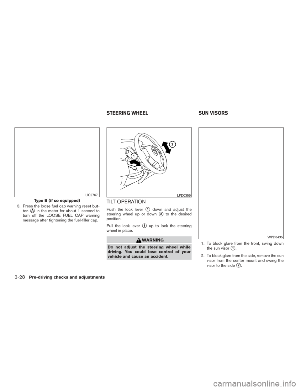
TILT OPERATION
Push the lock lever�1down and adjust the
steering wheel up or down
�2to the desired
position.
Pull the lock lever
�1up to lock the steering
wheel in place.
WARNING
Do not adjust the steering wheel while
driving. You could lose control of your
vehicle and cause an accident. 1. To block glare from the front, swing down
the sun visor�1.
2. To block glare from the side, remove the sun visor from the center mount and swing the
visor to the side
�2.
Type B (if so equipped)
LIC2767LPD0355
WPD0435
STEERING WHEEL SUN VISORS
3-28Pre-driving checks and adjustments
Page 152 of 414
3. Slide the extension�3sun visor (if so
equipped) in or out as needed.
CAUTION
● Do not store the sun visor before return-
ing the extension to its original
position.
● Do not pull the extension sun visor forc-
ibly downward.
VANITY MIRRORS (if so equipped)
To access the vanity mirror, pull the sun visor
down and slide the mirror cover open. Some
vanity mirrors are illuminated and turn on when
the mirror cover is open.
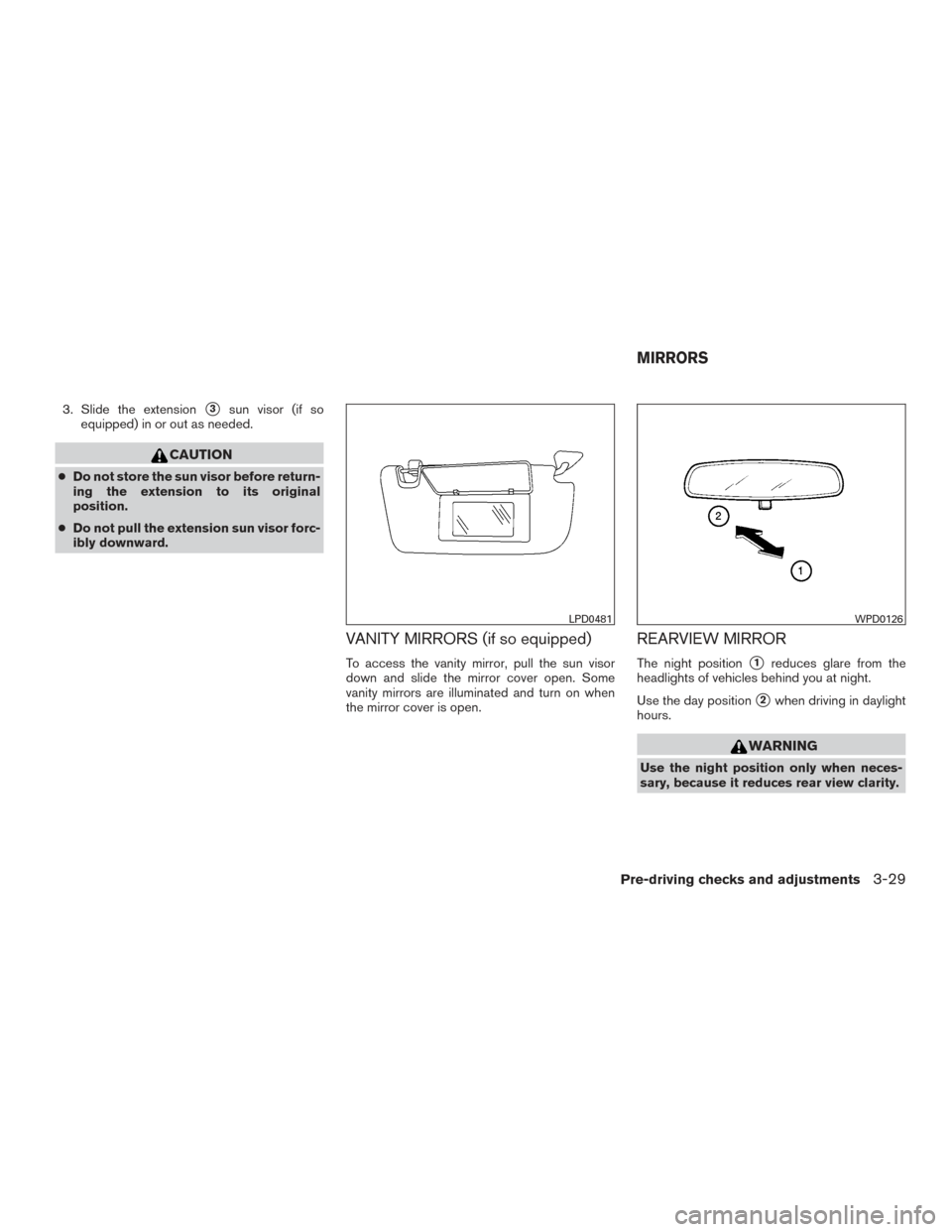
REARVIEW MIRROR
The night position�1reduces glare from the
headlights of vehicles behind you at night.
Use the day position
�2when driving in daylight
hours.
WARNING
Use the night position only when neces-
sary, because it reduces rear view clarity.
LPD0481WPD0126
MIRRORS
Pre-driving checks and adjustments3-29
Page 153 of 414

OUTSIDE MIRRORS
WARNING
●Do not adjust the mirrors while driving.
You could lose control of your vehicle
and cause an accident.
● Objects viewed in the outside mirror on
the passenger side are closer than they
appear. Be careful when moving to the
right. Using only this mirror could cause
an accident. Use the inside mirror or
glance over your shoulder to properly
judge distances to other objects. The outside mirror remote control only operates
when the ignition switch is placed in the ACC or
ON position.
Move the small switch
�1to select the right or left
mirror. Adjust each mirror to the desired position
using the large switch
�2.
Manual folding outside mirrors
Pull the outside mirror toward the door to fold it.
Heated mirrors (if so equipped)
Some outside mirrors can be heated to defrost,
defog, or de-ice for improved visibility. For addi-
tional information, refer to “Rear window and
outside mirror (if so equipped) defroster switch”
in the “Instruments and controls” section of this
manual.
LPD0237LPD0259
3-30Pre-driving checks and adjustments
Page 157 of 414

WARNING
●Positioning of the heating or air condi-
tioning controls and display controls
should not be done while driving in or-
der that full attention may be given to
the driving operation.
● Do not disassemble or modify this sys-
tem. If you do, it may result in accidents,
fire, or electrical shock.
● Do not use this system if you notice any
abnormality, such as a frozen screen or
lack of sound. Continued use of the
system may result in accident, fire or
electric shock.
● In case you notice any foreign object in
the system hardware, spill liquid on it,
or notice smoke or smell coming from it,
stop using the system immediately. Ig-
noring such conditions may lead to ac-
cidents, fire or electrical shock. It is rec-
ommended that you visit a NISSAN
dealer for servicing.
1. MAP button*
2. Display screen
3.
button**
4.
button 5.
(brightness control) button
6. BACK button
7. AUDIO button / TUNE knob
8. ON•OFF button / VOL (volume) control knob
LHA3621
CONTROL PANEL BUTTONS —
COLOR SCREEN WITH NAVIGATION
SYSTEM (if so equipped)
4-4Monitor, climate, audio, phone and voice recognition systems