Page 429 of 671

CAUTION
●After using the E-lock system, or during
normal driving, turn the switch off to
prevent possible damage to drivetrain
components from extended use.
● Avoid quick starts while the E-lock sys-
tem is in operation. Otherwise, the
drivetrain components could be
damaged.
● When the E-lock system is in operation,
turning the vehicle becomes difficult.
This can be dangerous, especially at
high speeds. Doing so could damage
drivetrain components.
● Do not operate the E-lock system when
the vehicle is turning or when one side
wheel is rotating. Otherwise, the drive-
train components could be damaged.
● The E-lock system operates only when
the engine is running.
● In 4H mode, the E-lock system does not
operate when the E-lock system switch
is turned to the ON position. (The E-lock
system indicator light will flash.)
● Observe the above cautions. Otherwise,
loss of normal steering control may
result. When the ignition switch is in the OFF position,
ECO management display appears.
�1Previous 5 times (History)
�2Current fuel economy
�3Best fuel economy
The result of ECO evaluation is displayed 30 sec-
onds after the ignition switch is placed in the ON
position and the vehicle is driven at least
1/3 miles (500 meters) .
�1The average fuel economy for the previous 5
times will be displayed.
�2The average fuel economy since the last
reset will be displayed.
�3The best fuel economy of the past history will
be displayed.
The ECO drive report can be set to be ON or
OFF.
Page 433 of 671
When the ABS senses that one or more wheels
are close to locking up, the actuator rapidly ap-
plies and releases hydraulic pressure. This action
is similar to pumping the brakes very quickly. You
may feel a pulsation in the brake pedal and hear a
noise from under the hood or feel a vibration from
the actuator when it is operating. This is normal
and indicates that the ABS is operating properly.
However, the pulsation may indicate that road
conditions are hazardous and extra care is re-
quired while driving.
BRAKE ASSIST
When the force applied to the brake pedal ex-
ceeds a certain level, the brake assist is activated
generating greater braking force than a conven-
tional brake booster even with light pedal force.
Page 436 of 671

WARNING
●Never rely solely on the hill descent
control system to control vehicle speed
when driving on steep downhill grades.
Always drive carefully and attentively
when using the hill descent control sys-
tem and decelerate the vehicle speed by
depressing the brake pedal if neces-
sary. Be especially careful when driving
on frozen, muddy or extremely steep
downhill roads. Failure to control ve-
hicle speed may result in a loss of con-
trol of the vehicle and possible serious
injury or death.
● The hill descent control may not control
the vehicle speed on a hill under all load
or road conditions. Always be prepared
to depress the brake pedal to control
vehicle speed. Failure to do so may re-
sult in a collision or serious personal
injury. The hill descent control system can only be acti-
vated when the 4H or 4LO switch is engaged.
The hill descent control system helps maintain
vehicle speed when driving under 15 mph
(25 km/h) on steeper downhill grades. Hill de-
scent control is useful when engine braking alone
cannot control vehicle speed. Hill descent con-
trol applies the vehicle brakes to control vehicle
speed allowing the driver to concentrate on
steering while reducing the burden of brake and
accelerator operation.
If the hill descent control light is blinking, the hill
descent control is engaged; however, the hill
descent control will not control the vehicle
speed.
● Once the system is activated, the indicator
light will remain on in the instrument panel.
For additional information, refer to “Hill de-
scent control system ON indicator light” in
the “Instruments and controls” section of this
manual.
● You may hear a noise from under the hood or
feel a vibration from the actuator when it is
operating. This indicates that the HDC sys-
tem is working properly. If the accelerator or brake pedal is depressed
while the hill descent control system is on, the
system will stop operating temporarily. As soon
as the accelerator or brake pedal is released, the
hill descent control system begins to function
again if the hill descent control operating condi-
tions are fulfilled.
For the best results, when descending steep
downhill grades, the hill descent control switch
should be ON and the shift lever in M1 (First) for
engine braking.
HILL DESCENT CONTROL SYSTEM (if
so equipped)
Starting and driving5-59
Page 437 of 671

WARNING
●Never rely solely on the hill start assist
system to prevent the vehicle from mov-
ing backward on a hill. Always drive
carefully and attentively. Depress the
brake pedal when the vehicle is stopped
on a steep hill. Be especially careful
when stopped on a hill on frozen or
muddy roads. Failure to prevent the ve-
hicle from rolling backwards may result
in a loss of control of the vehicle and
possible serious injury or death.
● The hill start assist system is not de-
signed to hold the vehicle at a standstill
on a hill. Depress the brake pedal when
the vehicle is stopped on a steep hill.
Failure to do so may cause the vehicle
to roll backwards and may result in a
collision or serious personal injury.
● The hill start assist may not prevent the
vehicle from rolling backwards on a hill
under all load or road conditions. Al-
ways be prepared to depress the brake
pedal to prevent the vehicle from rolling
backwards. Failure to do so may result
in a collision or serious personal injury. When the vehicle is stopped on a hill, the hill start
assist system automatically keeps the brakes ap-
plied. This helps prevents the vehicle from rolling
backward in the time it takes the driver to release
the brake pedal and apply the accelerator when
the vehicle is stopped on a hill.
Hill start assist will operate automatically under
the following conditions:
● The shift lever is shifted to a forward or
reverse gear.
● The vehicle is stopped completely on a hill
by applying the brake.
The maximum holding time is 2 seconds. After
2 seconds the vehicle will begin to roll back and
hill start assist will stop operating completely.
Hill start assist will not operate when the shift
lever is shifted into N (Neutral) or P (Park) or on a
flat and level road. When the VDC warning light
illuminates in the meter, the hill start assist system
will not operate. The sonar (parking sensor) system sounds a tone
to inform the driver of obstacles near the bumper.
When the “DISPLAY” key is ON, the sonar view
will automatically appear in the meter.
Page 440 of 671
HOW TO ENABLE/DISABLE THE
SONAR SYSTEM
The system is automatically activated when the
ignition is in the ON position and the shift lever is
in the R (Reverse) position.
Perform the following steps to enable or disable
the sonar system:1. Press the sonar switch (the orange light will go out) to turn the system off.
2. To turn the system back on, press the switch (the orange light will illuminate) and the sys-
tem will be enabled.
NOTE: ● The system will automatically be turned on
when the engine is restarted.
SONAR LIMITATIONS
Page 447 of 671
Push the switch on to warn other drivers when
you must stop or park under emergency condi-
tions. All turn signal lights flash.
Page 448 of 671
TIRE PRESSURE MONITORING
SYSTEM (TPMS)
This vehicle is equipped with TPMS. It monitors
tire pressure of all tires except the spare. When
the low tire pressure warning light is lit, and the
CHECK TIRE PRESSURE warning appears in
the vehicle information display, one or more of
your tires is significantly under-inflated. If
equipped, the system also displays pressure of
all tires (except the spare tire) on the display
screen by sending a signal from a sensor that is
installed in each wheel. If the vehicle is being
driven with low tire pressure, the TPMS will acti-
vate and warn you of it by the low tire pressure
warning light. This system will activate only when
the vehicle is driven at speeds above 16 mph
(25 km/h). For additional information, refer to
“Warning lights, indicator lights and audible re-
minders” in the “Instruments and controls” sec-
tion and “Tire Pressure Monitoring System
(TPMS)” in the “Starting and driving” section of
this manual.
Page 450 of 671
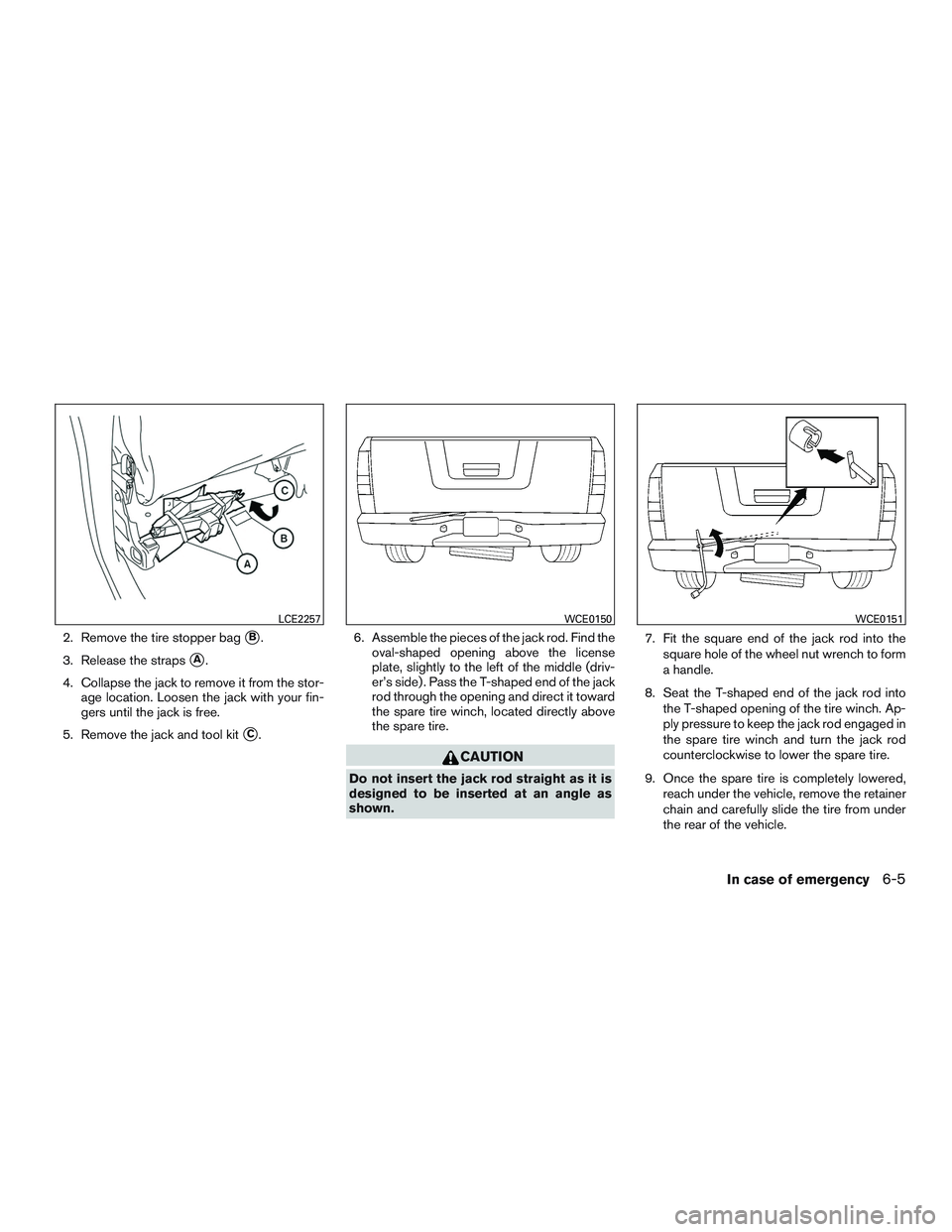
2. Remove the tire stopper bag�B.
3. Release the straps
�A.
4. Collapse the jack to remove it from the stor- age location. Loosen the jack with your fin-
gers until the jack is free.
5. Remove the jack and tool kit
�C. 6. Assemble the pieces of the jack rod. Find the
oval-shaped opening above the license
plate, slightly to the left of the middle (driv-
er’s side) . Pass the T-shaped end of the jack
rod through the opening and direct it toward
the spare tire winch, located directly above
the spare tire.

 position.
Perform the following steps to")


This vehicle is equipped with TPMS. It monitors
tire pressure of all tires except the spare. When
the low tire pressure warning light is lit, and the
CHECK TIRE")