Page 509 of 671
�3Tire ply composition and material
The number of layers or plies of rubber-
coated fabric in the tire. Tire manufactur-
ers also must indicate the materials in the
tire, which include steel, nylon, polyester
and others.
�4Maximum permissible inflation pres-
sure
This number is the greatest amount of air
pressure that should be put in the tire. Do
not exceed the maximum permissible in-
flation pressure.
�5Maximum load rating
This number indicates the maximum load
in kilograms and pounds that can be car-
ried by the tire. When replacing the tires
on the vehicle, always use a tire that has
the same load rating as the factory in-
stalled tire.
�6Term of “tubeless” or “tube type”
Indicates whether the tire requires an in-
ner tube (“tube type”) or not (“tubeless”) .
�7The word “radial”
The word “radial” is shown if the tire has
radial structure.
�8Manufacturer or brand name
Manufacturer or brand name is shown.
Other Tire-related Terminology
In addition to the many terms that are
defined throughout this section, Intended
Outboard Sidewall is (1) the sidewall that
contains a whitewall, bears white lettering
or bears manufacturer, brand, and/or
model name molding that is higher or
deeper than the same molding on the
other sidewall of the tire, or (2) the out-
ward facing sidewall of an asymmetrical
tire that has a particular side that must
always face outward when mounted on a
vehicle.
TYPES OF TIRES
WARNING
● When changing or replacing tires, be
sure all four tires are of the same type
(i.e., Summer, All Season or Snow) and
construction. A NISSAN dealer may be
able to help you with information about
tire type, size, speed rating and
availability.
● Replacement tires may have a lower
speed rating than the factory equipped
tires, and may not match the potential
maximum vehicle speed. Never exceed
the maximum speed rating of the tire.
● Replacing tires with those not originally
specified by NISSAN could affect the
proper operation of the low tire pres-
sure warning system.
● For additional information regarding
tires, refer to “Important Tire Safety In-
formation” (US) or “Tire Safety Informa-
tion” (Canada) in the Warranty Informa-
tion Booklet.
8-38Do-it-yourself
Page 568 of 671
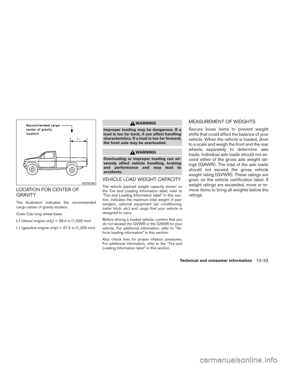
LOCATION FOR CENTER OF
GRAVITY
The illustration indicates the recommended
cargo center of gravity location.
Crew Cab long wheel base:
L1 (diesel engine only) = 39.4 in (1,000 mm)
L1 (gasoline engine only) = 47.2 in (1,200 mm)
WARNING
Improper loading may be dangerous. If a
load is too far back, it can affect handling
characteristics. If a load is too far forward,
the front axle may be overloaded.
WARNING
Overloading or improper loading can ad-
versely affect vehicle handling, braking
and performance and may lead to
accidents.
VEHICLE LOAD WEIGHT CAPACITY
The vehicle payload weight capacity shown on
the Tire and Loading Information label, refer to
“Tire and Loading Information label” in this sec-
tion, indicates the maximum total weight of pas-
sengers, optional equipment (air conditioning,
trailer hitch, etc) and cargo that your vehicle is
designed to carry.
Before driving a loaded vehicle, confirm that you
do not exceed the GVWR or the GAWR for your
vehicle. For additional information, refer to “Ve-
hicle loading information” in this section.
Also check tires for proper inflation pressures.
For additional information, refer to the “Tire and
Loading Information label” in this section.
MEASUREMENT OF WEIGHTS
Secure loose items to prevent weight
shifts that could affect the balance of your
vehicle. When the vehicle is loaded, drive
to a scale and weigh the front and the rear
wheels separately to determine axle
loads. Individual axle loads should not ex-
ceed either of the gross axle weight rat-
ings (GAWR) . The total of the axle loads
should not exceed the gross vehicle
weight rating (GVWR) . These ratings are
given on the vehicle certification label. If
weight ratings are exceeded, move or re-
move items to bring all weights below the
ratings.
WTI0195
Technical and consumer information10-33
Page 582 of 671
8. Rotate the safety chain anchor attachments90° until the center of the anchor seats into
place. NOTE:
Removal of the gooseneck hitch ball and
safety chain anchor attachments are in the
reverse order of installation. To remove
safety chain anchor attachment, lift the
center
�1, rotate 90°, and lift safety chain
anchor attachment away.
Tire pressures
● When towing a trailer, inflate the ve-
hicle tires to the recommended cold
tire pressure indicated on the Tire
and Loading Information label. ●
Trailer tire condition, size, load rating
and proper inflation pressure should
be in accordance with the trailer and
tire manufacturer’s specifications.
Safety chains
Always use suitable safety chains between your
vehicle and the trailer. The safety chains should
be crossed and should be attached to the hitch,
not to the vehicle bumper or axle. The safety
chains can be attached to the bumper if the hitch
ball is mounted to the bumper. Be sure to leave
enough slack in the chains to permit turning
corners.
LTI2212LTI2192
Technical and consumer information10-47