Page 21 of 671
Warninglight Name Page
Supplemental air
bag warning light 2-28
Water in Fuel warn-
ing light (if so
equipped)2-28
Indicator
light Name Page
Electronic locking
rear differential (E-
Lock) system ON
indicator light (if so
equipped) 2-29
Engine start opera-
tion indicator (if so
equipped)
2-29
Front fog light indi-
cator light (if so
equipped)2-29
Indicator
light Name Page
Front passenger air
bag status light (if
so equipped) 2-29
High beam indicator
light (blue)
2-29
Hill descent control
system ON indicator
light (if so equipped)2-29
Malfunction Indica-
tor Light (MIL) (yel-
low) (For Gas en-
gines only)2-30
Security indicator
light
2-30
Side light and head-
light indicator light
(green) (if so
equipped)2-31
Indicator
light Name Page
Slip indicator light 2-31
TOW mode ON in-
dicator light 2-31
Turn signal/hazard
indicator lights2-31
Vehicle Dynamic
Control (VDC) OFF
indicator light2-31
0-12Illustrated table of contents
Page 28 of 671

Operating tips
●The power seat motor has an auto-reset
overload protection circuit. If the motor
stops during operation, wait 30 seconds
then reactivate")
FRONT POWER SEAT ADJUSTMENT
(if so equipped)
Operating tips
●The power seat motor has an auto-reset
overload protection circuit. If the motor
stops during operation, wait 30 seconds
then reactivate the switch.
● Do not operate the power seat switch for a
long period of time when the engine is off.
This will discharge the battery.
For additional information, refer to “Automatic
drive positioner” in the “Pre-driving checks and
adjustments” section of this manual.
Forward and backward
Moving the switch forward or backward will slide
the seat forward or backward to the desired
position.
Reclining
Move the recline switch backward until the de-
sired angle is obtained. To bring the seatback
forward again, move the switch forward and
move your body forward. The seatback will move
forward. The reclining feature allows adjustment of the
seatback for occupants of different sizes for
added comfort and to help obtain proper seat
belt fit. For additional information, refer to “Pre-
cautions on seat belt usage” in this section. Also,
the seatback can be reclined to allow occupants
to rest when the vehicle is stopped and the shift
lever is in P (Park) .
LRS2743
Safety—Seats, seat belts and supplemental restraint system1-5
Page 104 of 671

2 Instruments and controls
Instrument panel...................................2-4
Meters and gauges ................................2-6
Speedometer and odometer .....................2-7
Tachometer ....................................2-9
Engine coolant temperature gauge ...............2-9
Fuel gauge ................................... 2-10
Auxiliary gauges (if so equipped) ................2-11
Diesel Exhaust Fluid (DEF) Level
(if so equipped) ............................... 2-12
Off-road monitor (if so equipped) ................2-13
Trip computer (if so equipped) ..................2-13
Compass (if so equipped) ......................... 2-18
Warning lights, indicator lights and audible
reminders ........................................ 2-21
Checking lights ............................... 2-22
Warning lights ................................ 2-22
Indicator lights ................................ 2-29
Audible reminders ............................. 2-31
Vehicle information display (if so equipped) ..........2-32
How to use the vehicle information display .......2-32
Startup display ................................ 2-33
Settings ...................................... 2-33
Vehicle information display warnings and
indicators ..................................... 2-41Diesel warnings and indicators
(if so equipped)
............................... 2-46
Security systems ................................. 2-47
Vehicle security system ......................... 2-47
NISSAN vehicle immobilizer system .............2-48
Wiper and washer switch ......................... 2-49
Switch operation .............................. 2-49
Rain-sensing auto wiper system
(if so equipped) ............................... 2-51
Rear window and/or outside mirror defroster switch
(if so equipped) .................................. 2-52
Headlight switch ................................. 2-53
Headlight control switch ........................ 2-53
Daytime running light system
(if so equipped) ............................... 2-56
Instrument brightness control ...................2-56
Turn signal switch ................................ 2-57
T
urn signal .................................... 2-57
Lane change signal ............................ 2-57
Fog light switch (if so equipped) ...................2-57
Horn ............................................ 2-58
Cargo lamp switch ................................ 2-58
Climate controlled seat switches (if so equipped) ....2-58
Heated seat switches (if so equipped) ..............2-60
Page 109 of 671
1. Tachometer
2. Warning and indicator lights
3. Vehicle information displayOdometer
Outside temperature display 4. Speedometer
5. Fuel gauge
6. Engine coolant temperature gauge
Type A (if so equipped)
LIC3100
METERS AND GAUGES
2-6Instruments and controls
Page 110 of 671
1. Tachometer
2. Warning and indicator lights
3. Speedometer
4. Fuel gauge5. Trip computer
Odometer
Outside temperature display
6. Engine coolant temperature gauge
SPEEDOMETER AND ODOMETER
This vehicle is equipped with a speedometer and
odometer. The speedometer is located on the
right side of the meter cluster. The odometer is
located in the vehicle information display (Type A)
(if so equipped) or the trip computer (Type B) (if
so equipped) to the left of the speedometer and
can be accessed with the vehicle in the ON
position.
Type B (if so equipped)
LIC3497
Instruments and controls2-7
Page 112 of 671
Changing the display
Pushing the TRIP RESET
�3switch on the left
side of the instrument panel changes the display
as follows:
ODO →Trip
→Trip→ODO
Resetting the trip odometer
Pushing the TRIP RESET switch
�3for about
2 seconds resets the currently displayed trip
odometer to zero.
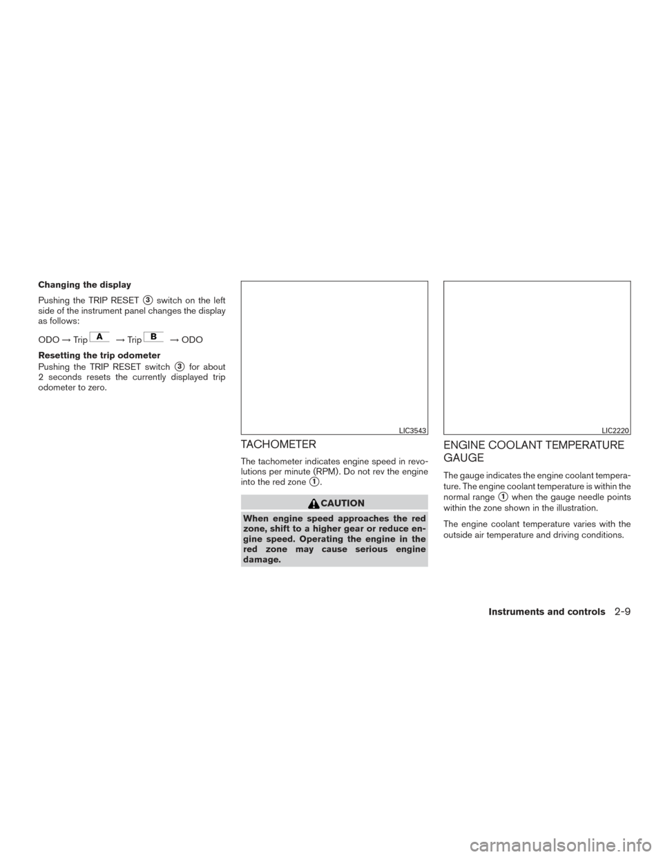
TACHOMETER
The tachometer indicates engine speed in revo-
lutions per minute (RPM) . Do not rev the engine
into the red zone
�1.
CAUTION
When engine speed approaches the red
zone, shift to a higher gear or reduce en-
gine speed. Operating the engine in the
red zone may cause serious engine
damage.
ENGINE COOLANT TEMPERATURE
GAUGE
The gauge indicates the engine coolant tempera-
ture. The engine coolant temperature is within the
normal range
�1when the gauge needle points
within the zone shown in the illustration.
The engine coolant temperature varies with the
outside air temperature and driving conditions.
LIC3543LIC2220
Instruments and controls2-9
Page 113 of 671
 end of the normal
range, reduce vehicle speed to decrease
temperature. If the gauge is over the nor-
mal range, stop the vehicle a")
CAUTION
If the gauge indicates coolant tempera-
ture near the hot (H) end of the normal
range, reduce vehicle speed to decrease
temperature. If the gauge is over the nor-
mal range, stop the vehicle as soon as
safely possible. If the engine is over-
heated, continued operation of the vehicle
may seriously damage the engine. For ad-
ditional information, refer to “If your ve-
hicle overheats” in the “In case of emer-
gency” section of this manual for
immediate action required.
FUEL GAUGE
The gauge indicates theapproximatefuel level
in the tank.
The gauge may move slightly during braking,
turning, acceleration, or going up or down hills.
The gauge needle returns to 0 (Empty) after the
ignition switch is placed in the OFF position.
The low fuel warning light comes on when the
amount of fuel in the tank is getting low.
Refill the fuel tank before the gauge regis-
ters 0 (Empty) . The
indicates that the fuel-filler door is
located on the driver’s side of the vehicle.
CAUTION
● If the vehicle runs out of fuel, theMalfunction Indicator Light (MIL) may
come on. Refuel as soon as possible.
After a few driving trips. the
light
should turn off. If the light remains on
after a few driving trips, have the vehicle
inspected. It is recommended that you
visit a NISSAN dealer for this service.
● For additional information, refer to
“Malfunction Indicator Light (MIL)” in
this section.
LIC2222
2-10Instruments and controls
Page 114 of 671

1. Exhaust temperature gauge (if so equipped)
2. Automatic Transmission fluid temperaturegauge
3. Turbo meter (if so equipped)
4. Engine oil pressure gauge
5. Engine")
AUXILIARY GAUGES (if so equipped)
1. Exhaust temperature gauge (if so equipped)
2. Automatic Transmission fluid temperaturegauge
3. Turbo meter (if so equipped)
4. Engine oil pressure gauge
5. Engine oil temperature gauge
6. Voltmeter Exhaust temperature gauge (if so
equipped)
For additional information, refer to the “Titan Die-
sel Owner’s Manual”.
Automatic Transmission fluid temperature
gauge
This gauge indicates the temperature of the au-
tomatic transmission fluid.
CAUTION
●
This gauge is not designed to indicate
low automatic transmission fluid level.
Use the dipstick to check the fluid level.
For additional information, refer to “6-
speed automatic transmission fluid” in
the “Do-it-yourself” section of this
manual.
● If the gauge indicates automatic trans-
mission fluid temperature over the nor-
mal range, stop the vehicle as soon as
safely possible. It is recommended that
you have the vehicle checked by a
NISSAN dealer. Continued operation of
the vehicle may seriously damage the
transmission.
Turbo meter (if so equipped)
For additional information, refer to the “Titan Die-
sel Owner’s Manual”.
Engine oil pressure gauge
The gauge indicates the engine lubrication sys-
tem oil pressure while the engine is running. The
bar should be in the middle of the gauge when
the engine is running.
LIC3390
Instruments and controls2-11
2-28
Indicator
light Name Page
Electronic locking
rear differential (E-
Lock) system ON
ind")