Page 17 of 671
Cummins 5.0 L engine
1. Windshield-washer fluid reservoir(P. 8-13)
2. Fuse box (P. 8-21)
3. Fuse/Fusible link box (P. 8-21)
4. Engine coolant reservoir*
5. Fuel filter (Stage 2)*
6. Engine oil filler cap*
7. Brake fluid reservoir (P. 8-13)
8. Air cleaner*
9. Battery (P. 8-14)
10. Power steering fluid reservoir (P. 8-12)
11. Radiator cap*
12. Engine oil dipstick*
13. Drive belt location*
14. Fuse/Fusible link box (P. 8-21)
15. Battery (P. 8-14)
*: Refer to the separate Titan Diesel Owner’s
Manual.
Refer to the page number indicated in pa-
rentheses for operating details.
LDI2870
ENGINE COMPARTMENT CHECK
LOCATIONS
0-8Illustrated table of contents
Page 18 of 671
VK56VD engine (non-XD model)
1. Windshield-washer fluid reservoir(P. 8-13)
2. Fuse box (P. 8-21)
3. Engine oil dipstick (P. 8-7)
4. Power steering fluid reservoir (P. 8-12)
5. Engine oil filler cap (P. 8-7)
6. Brake fluid reservoir (P. 8-13)
7. Air cleaner (P. 8-18)
8. Fuse/Fusible link box (P. 8-21)
9. Drive belt location (P. 8-17)
10. Radiator cap (P. 8-5)
11. Battery (P. 8-14)
12. Engine coolant reservoir (P. 8-5)
Refer to the page number indicated in pa-
rentheses for operating details.
LDI3056
Illustrated table of contents0-9
Page 19 of 671
VK56VD engine (XD model)
1. Windshield-washer fluid reservoir(P. 8-13)
2. Fuse box (P. 8-21)
3. Engine oil dipstick (P. 8-7)
4. Power steering fluid reservoir (P. 8-12)
5. Engine oil filler cap (P. 8-7)
6. Brake fluid reservoir (P. 8-13)
7. Air cleaner (P. 8-18)
8. Fuse/Fusible link box (P. 8-21)
9. Engine coolant reservoir (P. 8-5)
10. Drive belt location (P. 8-17)
11. Battery (P. 8-14)
12. Radiator cap (P. 8-5)
Refer to the page number indicated in pa-
rentheses for operating details.
LDI2973
0-10Illustrated table of contents
Page 176 of 671

Do not use the outlet located in the truck box with
accessories that exceed 120 volt. Do not use
double adapters or more than one electrical ac-
cessory. When the dual wall bed liner is installed
(if so equipped) , the power outlet is still acces-
sible through the access door in the bed liner.
CAUTION
●Operation of the 120 volt system with
the ignition in the ON position and the
engine not running (idle) will drain the
battery charge. This could lead to a
dead battery or no start condition.
● The outlet and plug may be hot during
or immediately after use.
● Use power outlets with the engine run-
ning to avoid discharging the vehicle
battery.
● Do not use double adaptors or more
than one electrical accessory.
● Avoid using power outlets when the air
conditioner, headlights or rear window
defroster is on.
● Before inserting or disconnecting a
plug, be sure the electrical accessory
being used is turned OFF. ●
Push the plug in as far as it will go. If
good contact is not made, the plug may
overheat or the internal temperature
fuse may open.
● When not in use, be sure to close the
cap. Do not allow water or any other
liquid to contact the outlet.
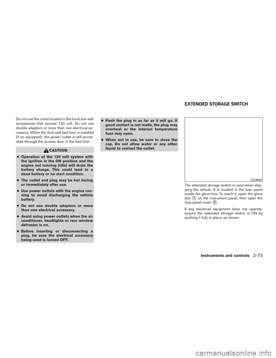
The extended storage switch is used when ship-
ping the vehicle. It is located in the fuse panel
inside the glove box. To reach it, open the glove
box
�1on the instrument panel, then open the
fuse panel cover
�2.
If any electrical equipment does not operate,
ensure the extended storage switch is ON by
pushing it fully in place, as shown.
LIC3502
EXTENDED STORAGE SWITCH
Instruments and controls2-73
Page 457 of 671

WARNING
Always follow the instructions below. Fail-
ure to do so could result in damage to the
charging system and cause personal
injury.1. If the booster battery is in another vehicle, position the two vehicles to bring their bat-
teries near each other.
Do not allow the two vehicles to touch.
2. Apply the parking brake. Move the shift lever to P (Park) . Switch off all unnecessary elec-
trical systems (lights, heater, air conditioner,
etc.) . 3. Remove the vent caps on the battery (if so
equipped) . Cover the battery with an old
cloth to reduce explosion hazard.
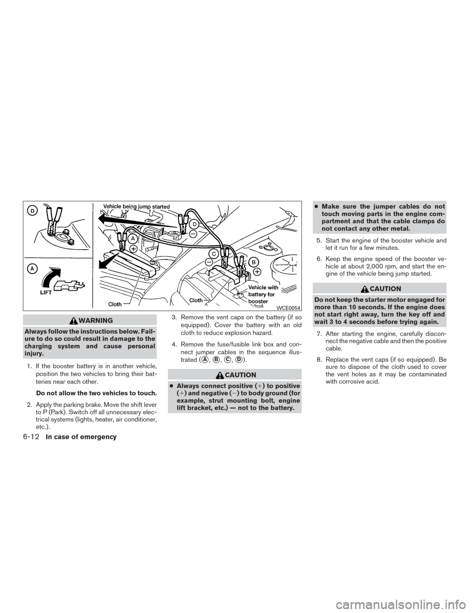
4. Remove the fuse/fusible link box and con- nect jumper cables in the sequence illus-
trated (
�A,�B,�C,�D).
CAUTION
●Always connect positive (�) to positive
(�) and negative (�) to body ground (for
example, strut mounting bolt, engine
lift bracket, etc.) — not to the battery. ●
Make sure the jumper cables do not
touch moving parts in the engine com-
partment and that the cable clamps do
not contact any other metal.
5. Start the engine of the booster vehicle and let it run for a few minutes.
6. Keep the engine speed of the booster ve- hicle at about 2,000 rpm, and start the en-
gine of the vehicle being jump started.
CAUTION
Do not keep the starter motor engaged for
more than 10 seconds. If the engine does
not start right away, turn the key off and
wait 3 to 4 seconds before trying again.
7. After starting the engine, carefully discon- nect the negative cable and then the positive
cable.
8. Replace the vent caps (if so equipped) . Be sure to dispose of the cloth used to cover
the vent holes as it may be contaminated
with corrosive acid.
WCE0054
6-12In case of emergency
Page 474 of 671
VK56VD engine (non-XD model)
1. Windshield-washer fluid reservoir
2. Fuse box
3. Engine oil dipstick
4. Power steering fluid reservoir
5. Engine oil filler cap
6. Brake fluid reservoir
7. Air cleaner
8. Fuse/Fusible link box
9. Drive belt location
10. Radiator cap
11. Battery
12. Engine coolant reservoir
LDI3056
ENGINE COMPARTMENT CHECK
LOCATIONS
Do-it-yourself8-3
Page 475 of 671
VK56VD engine (XD model)
1. Windshield-washer fluid reservoir
2. Fuse box
3. Engine oil dipstick
4. Power steering fluid reservoir
5. Engine oil filler cap
6. Brake fluid reservoir
7. Air cleaner
8. Fuse/Fusible link box
9. Engine coolant reservoir
10. Drive belt location
11. Battery
12. Radiator cap
For additional information on the Cummins 5.0L
engine, refer to the “Titan Diesel Owner’s
Manual”.
LDI2973
8-4Do-it-yourself
Page 492 of 671

Under some driving or climate conditions, occa-
sional brake squeak, squeal or other noise may
be heard. Occasional brake noise during light to
moderate stops is normal and does not affect the
function or performance of the brake system.
Proper brake inspection intervals should
be followed.For additional information on the
appropriate maintenance schedule regarding
brake inspections, refer to �Gasoline Standard
Maintenance� or�Diesel Standard Maintenance�
in the �Maintenance and schedules� section of
this manual.
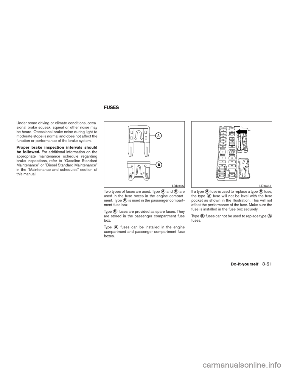
Two types of fuses are used. Type
�Aand�Bare
used in the fuse boxes in the engine compart-
ment. Type
�Bis used in the passenger compart-
ment fuse box.
Type
�Bfuses are provided as spare fuses. They
are stored in the passenger compartment fuse
box.
Type
�Afuses can be installed in the engine
compartment and passenger compartment fuse
boxes. If a type
�Afuse is used to replace a type�Bfuse,
the type
�Afuse will not be level with the fuse
pocket as shown in the illustration. This will not
affect the performance of the fuse. Make sure the
fuse is installed in the fuse box securely.
Type
�Bfuses cannot be used to replace type�A
fuses.
LDI0455LDI0457
FUSES
Do-it-yourself8-21