Page 78 of 491
 , the vehi-
cle’s hazard lamps (turn indicators) will
turn ON automatically.
Repair and replacement procedure
The")
NOTE:
In the event of a crash involving an air bag
deployment (side, front or both) , the vehi-
cle’s hazard lamps (turn indicators) will
turn ON automatically.
Repair and replacement procedure
The front air bags, side air bags, curtain air bags
and pretensioner(s) are designed to inflate on a
one-time-only basis. As a reminder, unless it is
damaged, the supplemental air bag warning light
remains illuminated after inflation has occurred.
These systems should be repaired and/or re-
placed as soon as possible. It is recommended
that you visit a NISSAN dealer for this service.
When maintenance work is required on the ve-
hicle, the front air bags, side air bags, curtain air
bags, pretensioner(s) and related parts should be
pointed out to the person performing the mainte-
nance. The ignition switch should always be
placed in the LOCK position when working under
the hood or inside the vehicle.
WARNING
●Once a front air bag, side air bag, or
curtain air bag has inflated, the air bag
module will not function again and
must be replaced. Additionally, the acti-
vated pretensioner(s) must also be re-
placed. The air bag module and preten-
sioner(s) should be replaced. It is
recommended that you visit a NISSAN
dealer for this service. However, the air
bag module and pretensioner(s) cannot
be repaired.
● The front air bag, side air bag, curtain
air bag systems and the pretensioner
system should be inspected if there is
any damage to the front end or side
portion of the vehicle. It is recom-
mended that you visit a NISSAN dealer
for this service.
● If you need to dispose of the supple-
mental air bag or pretensioner systems
or scrap the vehicle, it is recommended
that you visit a NISSAN dealer. Incorrect
disposal procedures could cause per-
sonal injury. ●
If there is an impact to your vehicle from
any direction, your Occupant Classifica-
tion Sensor (OCS) should be checked to
verify it is still functioning correctly. It is
recommended that you visit a NISSAN
dealer for this service. The OCS should
be checked even if no air bags deploy as
a result of the impact. Failure to verify
proper OCS function may result in an
improper air bag deployment resulting
in injury or death.
Safety—Seats, seat belts and supplemental restraint system1-59
Page 82 of 491
15. Ignition switch (if so equipped) (P. 5-8)Push-button ignition switch
(if so equipped) (P. 5-10)
16. Tilt/Telescopic steering (P. 3-28)
17. Hood release (P. 3-24) Fuel filler door release (P. 3-26)
18. ECO mode switch (if so equipped)
(P. 5-24)
Vehicle Dynamic Control (VDC) OFF
switch (if so equipped) (P. 2-47)
SPORT mode switch (if so equipped)
(P. 5-24)
19. Instrument brightness control (P. 2-41) Power mirror switch (P. 3-32)
Trunk release (P. 3-25)
* Refer to the separate Navigation System Own-
er’s Manual (if so equipped) .
Refer to the page number indicated in pa-
rentheses for operating details.
1. Tachometer
2. Coolant temperature gauge
3. Warning and indicator lights
4. Fuel gauge
5. Speedometer 6. Odometer
Twin trip odometer
Trip computer
Fuel Economy
ECO mode indicator
Outside temperature display
Type A (if so equipped)
LIC3415
METERS AND GAUGES
Instruments and controls2-3
Page 84 of 491
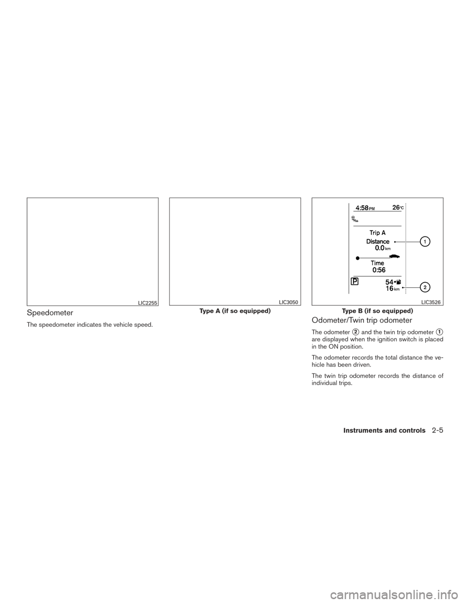
Speedometer
The speedometer indicates the vehicle speed.Odometer/Twin trip odometer
The odometer�2and the twin trip odometer�1
are displayed when the ignition switch is placed
in the ON position.
The odometer records the total distance the ve-
hicle has been driven.
The twin trip odometer records the distance of
individual trips.
LIC2255
Type A (if so equipped)
LIC3050
Type B (if so equipped)
LIC3526
Instruments and controls2-5
Page 86 of 491

The low tire pressure warning light remains illu-
minated until the tires are inflated to the recom-
mended COLD tire pressure. The CHECK TIRE
PRES warning message is displayed each time
the ignition switch is placed in the ON position as
long as the low tire pressure warning light re-
mains illuminated. For additional information, re-
fer to “Low tire pressure warning light” in the
“Instruments and controls” section, “Tire Pres-
sure Monitoring System (TPMS)” in the “Starting
and driving” section, and “Wheels and tires” in
the “Do-it-yourself” section of this manual.
TACHOMETER
The tachometer indicates engine speed in revo-
lutions per minute (rpm) . Do not rev engine into
the red zone
�1.
CAUTION
When engine speed approaches the red
zone, reduce engine speed. Operating the
engine in the red zone may cause serious
engine damage.
ENGINE COOLANT TEMPERATURE
GAUGE
NOTE:
The ignition switch must be placed in the
ON position for the gauge to give a reading.
The gauge indicates the engine coolant tempera-
ture. The engine coolant temperature is within the
normal range when the reading is within the zone
�Ashown in the illustration.
The engine coolant temperature varies with the
outside air temperature and driving conditions.
LIC2219
Type A (if so equipped)
LIC2414
Instruments and controls2-7
Page 87 of 491
 end of the normal
range, reduce vehicle speed to decrease
the temperature. If the gauge is over the
normal range, stop the vehic")
CAUTION
If the gauge indicates a coolant tempera-
ture near the hot (H) end of the normal
range, reduce vehicle speed to decrease
the temperature. If the gauge is over the
normal range, stop the vehicle as soon as
safely possible. If the engine is over-
heated, continued operation of the vehicle
may seriously damage the engine. For ad-
ditional information, refer to “If your ve-
hicle overheats” in the “In case of emer-
gency” section for immediate action
required
FUEL GAUGE
NOTE:
The ignition switch must be placed in the
ON position for the gauge to give a reading.
The gauge indicates theapproximatefuel level
in the tank.
The gauge may move slightly during braking,
turning, acceleration, or going up or down hills.
The low fuel warning light comes on when the
amount of fuel in the tank is getting low. Refill the fuel tank before the gauge regis-
ters 0 (Empty) .The arrow on the fuel pump symbol indi-
cates the fuel-filler location.
Type B (if so equipped)
LIC3427
Type A (if so equipped)
LIC2445
Type B (if so equipped)
LIC2222
2-8Instruments and controls
Page 88 of 491
CAUTION
●If the vehicle runs out of fuel, theMalfunction Indicator Light (MIL) may
come on. Refuel as soon as possible.
After a few driving trips. the
light
should turn off. If the light remains on
after a few driving trips, have the vehicle
inspected. It is recommended that you
visit a NISSAN dealer for this service.
● For additional information, refer to
“Malfunction Indicator Light (MIL)” in
this section.
TRIP COMPUTER (if so equipped)
When the ignition switch is placed in the ON
position, the modes of the trip computer can be
selected by pressing the
button on the
steering wheel. The following modes can be se-
lected:
● Trip A
● Trip B
● ECO Pedal Indicator
● Instant fuel economy
● Average fuel economy
● Average speed ●
Distance to empty
● Trip computer reset
Trip symbol: A or B
Trip A
Measures the distance of one specific trip
�1.
Trip B
Measures the distance of a second specific trip.
LIC3146
Instruments and controls2-9
Page 91 of 491

OUTSIDE TEMPERATURE DISPLAY
The outside temperature function provides a dis-
play of the outside temperature when the ignition
switch is placed in the ON position.
The display of positive temperatures is unsigned
(blank) , negative temperatures are prefixed with a
minus sign.
The outside temperature will always be visible on
the left side of the display.This unit measures terrestrial magnetism and in-
dicates heading direction of vehicle.
With the ignition switch in the ON position, press
the
button as described in the chart below
to activate various features of the automatic anti-
glare rearview mirror.
Press and hold
the
button for about: Feature:
(Press button again for about 1 sec-
ond to change settings)
1 second Compass display toggles on/off
8 seconds Automatic anti-glare/indicator light
toggles on/off
11 seconds Compass zone can be changed to
correct false compass readings
13 seconds Compass enters calibration mode
For additional information, refer to “Automatic
anti-glare rearview mirror” in the “Pre-driving
checks and adjustments” section of this manual.
COMPASS DISPLAY
Push thebutton for about 1 second when
the ignition key is in the ON position to toggle the
compass direction display
�1on or off. The dis-
play will indicate the direction of the vehicle’s
heading.
N: North
E: East
S: South
W: West
If the “CAL” or “C” icon is illuminated in the
compass display, calibrate the compass by driv-
ing the vehicle in three complete circles at less
than 8 km/h (5 mph) .
LIC3149WIC0904
COMPASS (if so equipped)
2-12Instruments and controls
Page 95 of 491

CHECKING LIGHTS
With all doors closed, apply the parking brake,
fasten the seat belts and place the ignition switch
in the ON position without starting the engine.
The following lights (if so equipped) will come on:
,or,,or
The following lights (if so equipped) will come on
briefly and then go off:
or,,,,,
SPORT ,
If any light does not come on or operate in a way
other than described, it may indicate a burned-
out bulb and/or a system malfunction. It is recom-
mended that you have the system checked by a
NISSAN dealer.
Some indicators and warnings are also displayed
on the vehicle information display between the
speedometer and tachometer. For additional in-
formation, refer to “Vehicle information display” in
this section.
WARNING LIGHTS
orAnti-lock Braking
System (ABS)
warning light
When the ignition switch is placed in the ON
position, the ABS warning light illuminates and
then turns off. This indicates the ABS is opera-
tional.
If the ABS warning light illuminates while the
engine is running or while driving, it may indicate
the ABS is not functioning properly. Have the
system checked. It is recommended that you visit
a NISSAN dealer for this service.
If an ABS malfunction occurs, the anti-lock func-
tion is turned off. The brake system then operates
normally but without anti-lock assistance. For
additional information, refer to “Brake system” in
the “Starting and driving” section of this manual.
orBrake warning light
This light functions for both the parking brake and
the foot brake systems.
Parking brake indicator
When the ignition switch is placed in the ON
position, the light comes on when the parking
brake is applied. Low brake fluid warning light
When the ignition switch is placed in the ON
position, the light warns of a low brake fluid level.
If the light comes on while the engine is running,
with the parking brake not applied, stop the ve-
hicle and perform the following:
1. Check the brake fluid level. Add brake fluid as necessary. For additional information, re-
fer to “Brake fluid” in the “Do-it-yourself”
section of this manual.
2. If the brake fluid level is correct, have the warning system checked. It is recommended
that you visit a NISSAN dealer for this ser-
vice.
WARNING
●Your brake system may not be working
properly if the warning light is on. Driv-
ing could be dangerous. If you judge it
to be safe, drive carefully to the nearest
service station for repairs. Otherwise,
have your vehicle towed because driv-
ing it could be dangerous.
● Pressing the brake pedal with the en-
gine stopped and/or a low brake fluid
level may increase your stopping dis-
tance and braking will require greater
pedal effort as well as pedal travel.
2-16Instruments and controls
 (P. 5-8)Push-button ignition switch
(if so equipped) (P. 5-10)
16. Tilt/Telescopic steering (P. 3-28)
17. Hood release (P. 3-24) Fuel filler door release (P. 3-26)")
 may
come on. Refuel as soon as possible.
After a few driving trips. the
light
should turn off. If the light remains on")