Page 159 of 547
 ............3-2
NISSAN Intelligent Key® (if so equipped) .........3-3
N")
3 Pre-driving checks and adjustments
Keys .............................................3-2Remote keyless entry (if so equipped) ............3-2
NISSAN Intelligent Key® (if so equipped) .........3-3
NISSAN Vehicle Immobilizer System keys .........3-4
Doors ............................................3-5
Locking with key ................................3-5
Locking with inside lock knob ....................3-6
Locking with power door lock switch . . . ..........3-6
Automatic door locks ...........................3-7
Child safety rear door lock .......................3-7
Remote keyless entry system (if so equipped) .........3-7
How to use remote keyless entry system ..........3-8
NISSAN Intelligent Key® (if so equipped) ...........3-11
Operating range ............................... 3-12
Door locks/unlocks precaution ..................3-13
NISSAN Intelligent Key® Operation .............3-14
How to use the remote keyless entry
function ...................................... 3-17
Warning signals ............................... 3-20
Troubleshooting guide ......................... 3-21
Remote Engine Start (if so equipped) ...............3-23
Remote engine start operating range . . . .........3-23
Remote starting the vehicle .....................3-24Extending engine run time
......................3-24
Canceling a remote start .......................3-24
Conditions the remote start will not work .........3-25
Hood ........................................... 3-26
Liftgate .......................................... 3-27
Operating the manual liftgate
(if so equipped) ............................... 3-27
Operating the power liftgate (if so equipped) .....3-28
Motion-Activated Liftgate (if so equipped) ........3-31
Power liftgate main switch ......................3-33
Liftgate release ................................ 3-33
Liftgate position setting ........................ 3-34
Fuel-filler door ................................... 3-34
Opener operation .............................. 3-34
Fuel-filler cap ................................. 3-35
Steering wheel ................................... 3-37
Manual operation .............................. 3-37
Sun
visors ....................................... 3-38
Vanity mirrors ................................. 3-38
Card holder (driver’s side only) ..................3-39
Mirrors .......................................... 3-39
Manual anti-glare rearview mirror
(if so equipped) ............................... 3-39
Page 160 of 547
Automatic anti-glare rearview mirror
(if so equipped)............................... 3-39
Outside mirrors ............................... 3-40
Automatic drive positioner (if so equipped) ..........3-41 Memory storage function
.......................3-42
Entry/exit function ............................. 3-43
System operation .............................. 3-43
Page 197 of 547
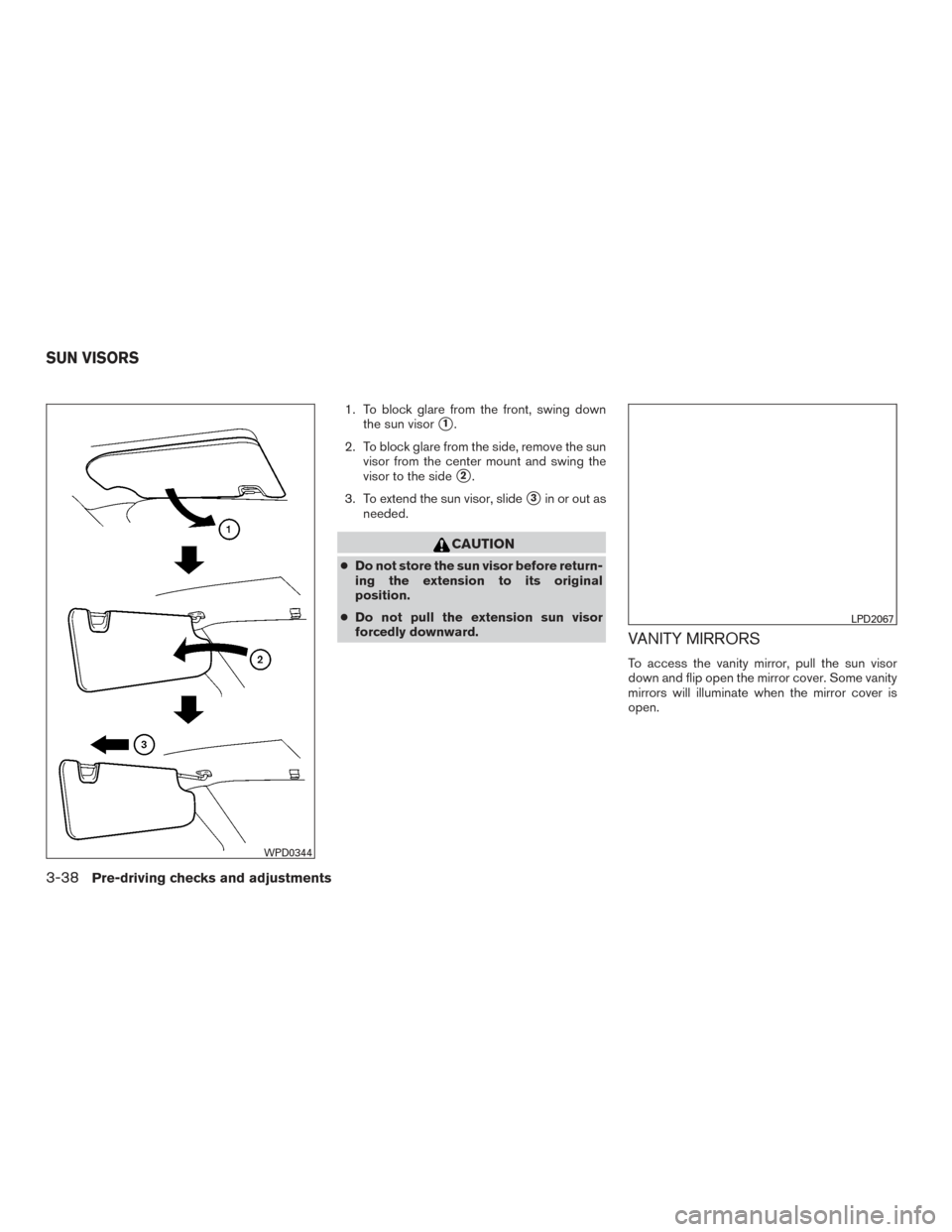
1. To block glare from the front, swing downthe sun visor
�1.
2. To block glare from the side, remove the sun visor from the center mount and swing the
visor to the side
�2.
3. To extend the sun visor, slide
�3in or out as
needed.
CAUTION
● Do not store the sun visor before return-
ing the extension to its original
position.
● Do not pull the extension sun visor
forcedly downward.
VANITY MIRRORS
To access the vanity mirror, pull the sun visor
down and flip open the mirror cover. Some vanity
mirrors will illuminate when the mirror cover is
open.
WPD0344
LPD2067
SUN VISORS
3-38Pre-driving checks and adjustments
Page 198 of 547

To access the card holder, slide card in the card
holder. Do not view information while operating
the vehicle.
MANUAL ANTI-GLARE REARVIEW
MIRROR (if so equipped)
Use")
CARD HOLDER (driver’s side only)
To access the card holder, slide card in the card
holder. Do not view information while operating
the vehicle.
MANUAL ANTI-GLARE REARVIEW
MIRROR (if so equipped)
Use the night position�1to reduce glare from
the headlights of vehicles behind you at night.
Use the day position
�2when driving in daylight
hours.
WARNING
Use the night position only when neces-
sary, because it reduces rear view clarity.
AUTOMATIC ANTI-GLARE
REARVIEW MIRROR (if so equipped)
The inside mirror is designed so that it automati-
cally dims during night time conditions and ac-
cording to the intensity of the headlights of the
vehicle following you. The automatic anti-glare
feature is activated when the ignition switch is in
the ON position.
The indicator light
�2will illuminate when the
automatic anti-glare feature is operating.
NOTE:
Do not hang any objects over the sensors
�1or apply glass cleaner to the sensors.
Doing so will reduce the sensitivity of the
sensors, resulting in improper operation.LPD2120WPD0126
MIRRORS
Pre-driving checks and adjustments3-39
Page 199 of 547

The indicator light will illuminate when the auto-
matic anti-glare feature is operating.
With the ignition switch in the ON position, press
the
button as described:
● To turn off the anti-glare feature, press
the
button. The indicator light will turn
off.
● To turn on the anti-glare feature, press
the
button again. The indicator light
will turn on. For additional information about the compass
�3
and compass features, refer to “Compass dis-
play” in the “Instruments and controls” section of
this manual.
For information on HomeLink® Universal Trans-
ceiver operation, refer to the “HomeLink® Uni-
versal Tranceiver” on the “Instruments and con-
trols” section of this manual.
OUTSIDE MIRRORS
The outside mirror remote control will operate
only when the ignition switch is in the ON posi-
tion.
Move the small switch
�1to select the left or right
mirror. Adjust each mirror to the desired position
using the large switch
�2.
Type A (if so equipped)
WPD0446
Type B (if so equipped)
LPD2419LPD2452
3-40Pre-driving checks and adjustments
Page 200 of 547
WARNING
●Objects viewed in the outside mirror on
the passenger side are closer than they
appear. Be careful when moving to the
right. Using only this mirror could cause
an accident. Use the inside mirror or
glance over your shoulder to properly
judge distances to other objects.
● Do not adjust the mirrors while driving.
You could lose control of your vehicle
and cause an accident.
Manual folding outside mirrors
Pull the outside mirror toward the door to fold it.
Heated mirrors (if so equipped)
Some outside mirrors can be heated to defrost,
defog, or de-ice for improved visibility. For addi-
tional information, refer to “Rear window and
outside mirror (if so equipped) defroster switch”
in the “Instruments and controls” section of this
manual. The automatic drive positioner system has two
features:
● Memory storage function
● Entry/exit function
LPD2084
AUTOMATIC DRIVE POSITIONER (if
so equipped)
Pre-driving checks and adjustments3-41
Page 201 of 547

MEMORY STORAGE FUNCTION
Two positions for the driver’s seat and outside
mirrors can be stored in the automatic drive po-
sitioner memory. Follow these procedures to use
the memory system.1. Place the ignition in the ON or OFF position (the vehicle should be stopped while setting
the memory) .
2. Adjust the driver’s seat and outside mirrors to the desired positions by manually operat-
ing each adjusting switch. For additional in-
formation, refer to “Seats” in the “Safety—
Seats, seat belts and supplemental restraint system” section of this manual and “Outside
mirrors” in this section.
3. Push the SET switch and, within 5 seconds, push the memory switch (1 or 2) .
4. The indicator light for the pushed memory switch will come on and stay on for approxi-
mately 5 seconds.
5. The chime will sound if the memory has been stored.
NOTE:
If a NEW memory position is stored in the
same memory switch, the previous memory
position will be overwritten by the new
stored position.
Confirming memory storage
Push the SET switch. ● If a memory position has not been stored in
the switch (1 or 2) the indicator light for the
respective switch will come ON for approxi-
mately 0.5 seconds. ●
If a memory position has been stored in the
switch (1 or 2) then the indicator light for the
respective switch will stay ON for approxi-
mately 5 seconds.
Linking a key fob to a stored memory
position
Each key fob can be linked to a stored memory
position (memory switch 1 or 2) with the follow-
ing procedure.
1. Follow steps 1-3 in the “Memory Storage Function” section for storing the memory
position.
2. The indicator light for the pushed memory switch will come on. While the indicator light
is on for 5 seconds, press the
button
on the key fob. The indicator light of the
linked memory switch will blink. After the
indicator light goes off, the key fob is linked
to that memory setting.
Once it is linked, when ignition switch is placed in
the OFF position, pressing the
button on
the key fob will move the driver’s seat and outside
mirrors to the linked memory switch position.
LPD2531
3-42Pre-driving checks and adjustments
Page 214 of 547
WARNING
Failure to follow the warnings and instruc-
tions for proper use of the RearView
Monitor system could result in serious in-
jury or death.●
RearView Monitor is a convenience fea-
ture and is not a substitute for proper
backing. Always turn and look out the
windows and check mirrors to be sure
that it is safe to move before operating
the vehicle. Always back up slowly. ●
The system is designed as an aid to the
driver in showing large stationary ob-
jects directly behind the vehicle, to help
avoid damaging the vehicle.
LHA4361
REARVIEW MONITOR (if so
equipped)
Monitor, climate, audio, phone and voice recognition systems4-11
............................... 3-39
Outside mirrors ............................... 3-40
Automatic drive positioner (if so equipped) ..........3-4")