Page 4 of 38

4. ROADSIDE ASSISTANCE . . . . . . . . . . . . . . . . . . . . . . . . . . . . . . . . . . . . . . . . . . . . . . . .
. . . . . RAG–22
4-1 JUMP STARTING . . . . . . . . . . . . . . . . . . . . . . . . . . . . . . . . . . . . . . . . . . . . . . . . . . . . . . . RAG–22 4-1.1 JUMP STARTING PROCEDURES . . . . . . . . . . . . . . . . . . . . . . . . . . . . . . . . . . . . . RAG–23
4-1.2 SHIFT SELECTOR LEVER LOCK RELEASE . . . . . . . . . . . . . . . . . . . . . . . . . . . . . . RAG–24
4-2 TOOLS INSTALLED IN THE VEHICLE . . . . . . . . . . . . . . . . . . . . . . . . . . . . . . . . . . . . . . . RAG–25
4-3 TOWING . . . . . . . . . . . . . . . . . . . . . . . . . . . . . . . . . . . . . . . . . . . . . . . . . . . . . . . . . . . . . . RAG–25 4-3.1 VEHICLE SPECIFICATIONS . . . . . . . . . . . . . . . . . . . . . . . . . . . . . . . . . . . . . . . . . . RAG–25
4-3.2 TOWING GUIDELINES . . . . . . . . . . . . . . . . . . . . . . . . . . . . . . . . . . . . . . . . . . . . . . RAG–26
4-3.3 USE OF VEHICLE EQUIPPED HOOKS FOR RECOVERY OPERATIONS . . . . . . . RAG–27
4-4 JACKING UP THE VEHICLE AND CHANGING A TIRE . . . . . . . . . . . . . . . . . . . . . . . . . . RAG–28
5. STORING THE VEHICLE . . . . . . . . . . . . . . . . . . . . . . . . . . . . . . . . . . . . . . . . . . . . . . . . . . . . . . RAG–32 5-1 DANGER SIGN EXAMPLE . . . . . . . . . . . . . . . . . . . . . . . . . . . . . . . . . . . . . . . . . . . . . . . . RAG–32
5-2 REMOVING THE SERVICE PLUG . . . . . . . . . . . . . . . . . . . . . . . . . . . . . . . . . . . . . . . . . . RAG–34
RAG–4
Page 25 of 38
4-2 Tools Installed in the Vehicle
The
tool kit is housed along with the jack located inside the rear cargo area.
The jack and tool kit are located in the storage compartment to the left. • Remove the storage door by pressing the two release tabs simultaneously.
• Remove jacking tools located inside the compartment as illustrated.
4-3 Towing
4-3.1 Vehicle Specifications Length
184.5
in. (4,686 mm)
Width 72.4 in. (1,840 mm)
Overall Height
(with roof rack) With All-Wheel drive 68.4 in. (1,737 mm)
With Front wheel drive 67.6 in. (1,717 mm)
Wheel Base 106.5 in. (2,706 mm)
Minimum ground clearance 7.4 in. (187 mm)
Overall vehicle weight 3,624 – 3,814 lbs. (1,644 – 1,730 kg)
(Weight varies by equipment and trim level.)
Front approach angle 17.4°
Rear departure angle 25.0° AAYIA0514ZZ
RAG–25
Page 28 of 38

4-4 Jacking Up the Vehicle and Changing a Tire
Always follow these instructions when jacking up the vehicle and changing a tire:
•
Never change a tire when the vehicle is on a slope, ice or slippery areas. Jack must be on
level ground.
• Make sure the parking brake is securely applied and shift selector is in P (Park) position.
• Never get under the vehicle while it is supported only by the jack. If it is necessary to work under the vehicle, support it with safety stands.
• Use the correct jack-up points. Never use any other part of the vehicle for jack support.
• Never jack up the vehicle more than necessary.
• Never use blocks on or under the jack.
• Do not start or run the engine while vehicle is on the jack. It may cause the vehicle to move. This is especially true for vehicles with limited slip differentials.
• Do not allow passengers to stay in the vehicle while it is on the jack.
• Never run the engine with a wheel(s) off the ground. It may cause the vehicle to move.
• Be sure to block the wheel diagonally opposite the wheel being removed as the vehicle may move and result in personal injury.
Failure to follow these instructions can result in serious personal injury or death and/or
vehicle damage.
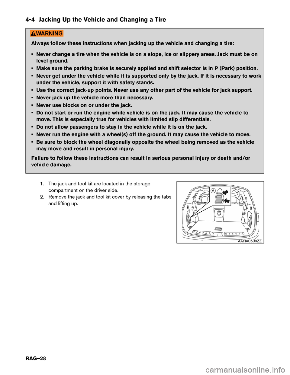
1. The jack and tool kit are located in the storagecompartment on the driver side.
2. Remove the jack and tool kit cover by releasing the tabs and lifting up. AAYIA0509ZZ
RAG–28
Page 31 of 38

11. Install new or repaired tire and hand-tighten the wheel
nuts with the wheel nut wrench in an alternating pattern. Always follow these instructions when changing a tire:
•
Incorrect wheel nuts or improperly tightened wheel
nuts can cause the wheel to become loose or come
off. This could cause an accident.
• Do not use oil or grease on the wheel studs or nuts. This could cause the nuts to become loose.
Failure to follow these instructions can result in serious
personal injury or death and/or vehicle damage.
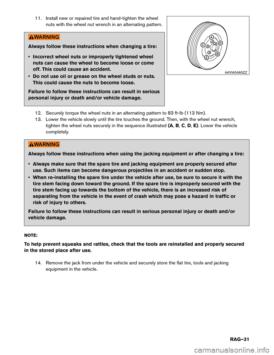
12. Securely torque the wheel nuts in an alternating pattern to 83 ft-lb (113 Nm) .
13. Lower the vehicle slowly until the tire touches the ground. Then, with the wheel nut wrench, tighten the wheel nuts securely in the sequence illustrated (A,B,C,D, E). Lower the vehicle
completely. Always follow these instructions when using the jacking equipment or after changing a tire:
•
Always make sure that the spare tire and jacking equipment are properly secured after
use. Such items can become dangerous projectiles in an accident or sudden stop.
• When re-installing the spare tire under the vehicle after use, be sure to secure it with the tire stem facing down toward the ground. If the spare tire is improperly secured with the
tire stem facing up towards the bottom of the vehicle, there is an increased risk of
separating from the vehicle in the event of crash which may pose a hazard in traffic or
risk of injury to others.
Failure to follow these instructions can result in serious personal injury or death and/or
vehicle damage.
NOTE:
To help prevent squeaks and rattles, check that the tools are reinstalled and properly secured
in the stored place after use. 14. Remove the jack from under the vehicle and securely store the flat tire, tools and jacking equipment in the vehicle. A
B
E D
C
AAYIA0460ZZ
RAG–31