2017 NISSAN QUEST mirror controls
[x] Cancel search: mirror controlsPage 88 of 520
2 Instruments and controls
Cockpit ........................................................................\
................ 2-3
Instrument panel ........................................................................\
2-4
Meters and gauges ................................................................... 2-5Meter/ring illumination and needle sweep .................... 2-5
Speedometer and odometer ............................................ 2-6
Tachometer ........................................................................\
... 2-7
Engine coolant temperature gauge ................................ 2-7
Fuel gauge ........................................................................\
.... 2-8
Compass (if so equipped) ...................................................... 2-8 Zone variation change procedure ................................ 2-10
Warning lights, indicator lights and
audible reminders ................................................................... 2-11 Checking lights ................................................................. 2-12
Warning lights ................................................................... 2-12
Indicator lights ................................................................... 2-16
Audible reminders ............................................................ 2-18
Vehicle information display .................................................. 2-19 Operational indicators ..................................................... 2-21
Maintenance indicators ................................................... 2-23
Trip computer .................................................................... 2-24
Security systems .................................................................... 2-28 Vehicle security system .................................................. 2-28
NISSAN vehicle immobilizer system ........................... 2-30
Wiper and washer switch .................................................... 2-31 Rear window wiper and washer switch ..................... 2-32 Rear window and outside mirror defroster switch ....... 2-33
Headlight and turn signal switch ....................................... 2-33
Xenon headlights (if so equipped) ............................ 2-33
Headlight switch ............................................................ 2-34
Turn signal switch .......................................................... 2-38
Fog light switch (if so equipped) .............................. 2-39
Horn ........................................................................\
.................. 2-39
Heated seats (if so equipped) ........................................... 2-39
Blind Spot Warning (BSW) switch (if so equipped) ..... 2-41
Vehicle Dynamic Control (VDC) OFF switch ................. 2-41
Power outlet ........................................................................\
.... 2-42
Storage ........................................................................\
............ 2-44 Cup holders ..................................................................... 2-44
Sunglasses holder ......................................................... 2-46
Glove box ........................................................................\
. 2-47
Instrument lower box (if so equipped) ..................... 2-47
Console box .................................................................... 2-47
Cargo floor box ............................................................... 2-48
Hooks ........................................................................\
........ 2-49
Roof rack (if so equipped) .......................................... 2-50
Coat hooks ...................................................................... 2-51
Sunshade (if so equipped) ................................................. 2-51
Windows ........................................................................\
......... 2-52
Power windows .............................................................. 2-52
Page 91 of 520
2-4Instruments and controls
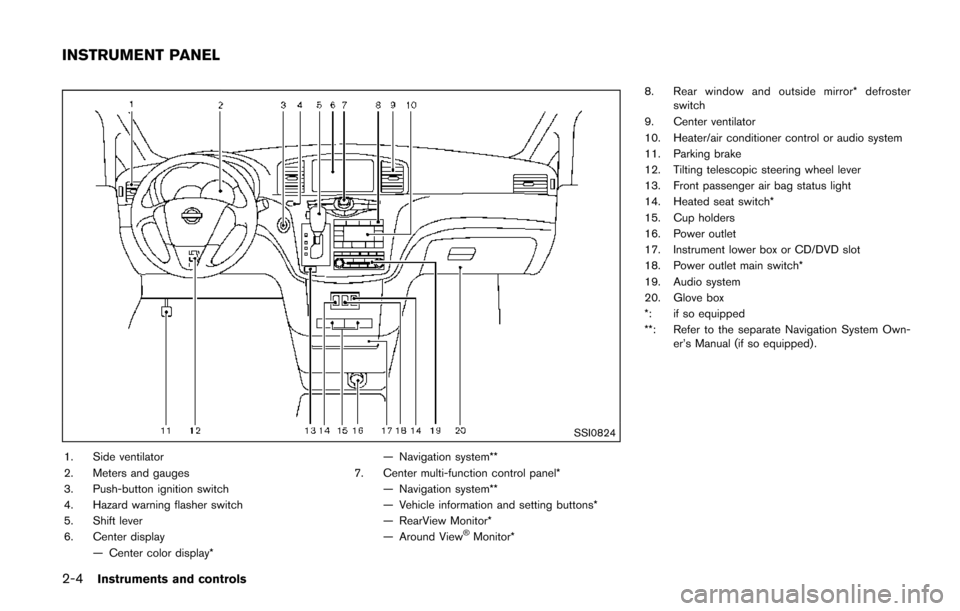
SSI0824
1. Side ventilator
2. Meters and gauges
3. Push-button ignition switch
4. Hazard warning flasher switch
5. Shift lever
6. Center display— Center color display* — Navigation system**
7. Center multi-function control panel* — Navigation system**
— Vehicle information and setting buttons*
— RearView Monitor*
— Around View
�ŠMonitor* 8. Rear window and outside mirror* defroster
switch
9. Center ventilator
10. Heater/air conditioner control or audio system
11. Parking brake
12. Tilting telescopic steering wheel lever
13. Front passenger air bag status light
14. Heated seat switch*
15. Cup holders
16. Power outlet
17. Instrument lower box or CD/DVD slot
18. Power outlet main switch*
19. Audio system
20. Glove box
*: if so equipped
**: Refer to the separate Navigation System Own- er’s Manual (if so equipped) .
INSTRUMENT PANEL
Page 97 of 520
2-10Instruments and controls
ZONE VARIATION CHANGE PROCE-
DURE
The difference between magnetic north and
geographical north is known as variance. In
some areas, this difference can sometimes be
great enough to cause false compass readings.
Follow these instructions to set the variance for
your particular location if this happens:
1. Push the
switch for more than 3
seconds. The current zone number will
appear in the display.
2. Find your current location and variance number on the zone map.
NOTE:
Use zone number 5 for Hawaii.
3. Push the
switch repeatedly until the
new zone number appears in the display,
then release the switch. After you release
the switch, the display will show a compass
direction within a few seconds.
.If the compass deviates from the correct indication soon after repeated adjust-
ment, have the compass checked. It is
recommended you visit a NISSAN dealer
for this service.
.The compass may not indicate the
correct compass point in tunnels or while
driving up or down a steep hill. (The compass returns to the correct com-
pass point when the vehicle moves to an
area where the geomagnetism is stabilized.)
CAUTION
.
Do not install a ski rack, antenna,
etc., which are attached to the
vehicle by means of a magnet. They
affect the operation of the compass.
. When cleaning the mirror, use a
paper towel or similar material
dampened with glass cleaner. Do
not spray glass cleaner directly on
the mirror as it may cause the liquid
cleaner to enter the mirror housing.
Page 120 of 520
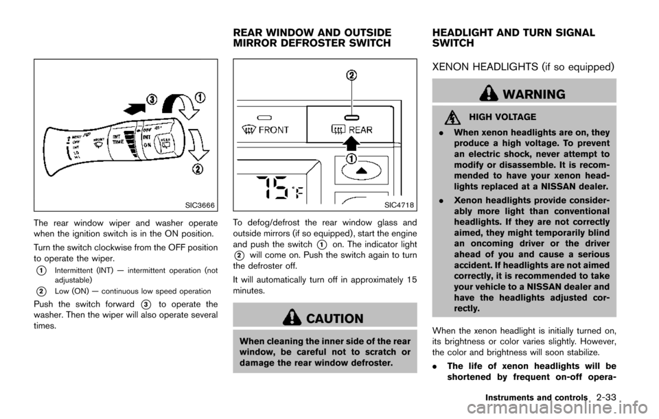
SIC3666
The rear window wiper and washer operate
when the ignition switch is in the ON position.
Turn the switch clockwise from the OFF position
to operate the wiper.
*1Intermittent (INT) — intermittent operation (not
adjustable)
*2Low (ON) — continuous low speed operation
Push the switch forward*3to operate the
washer. Then the wiper will also operate several
times.
SIC4718
To defog/defrost the rear window glass and
outside mirrors (if so equipped) , start the engine
and push the switch
*1on. The indicator light
*2will come on. Push the switch again to turn
the defroster off.
It will automatically turn off in approximately 15
minutes.
CAUTION
When cleaning the inner side of the rear
window, be careful not to scratch or
damage the rear window defroster.
XENON HEADLIGHTS (if so equipped)
WARNING
HIGH VOLTAGE
. When xenon headlights are on, they
produce a high voltage. To prevent
an electric shock, never attempt to
modify or disassemble. It is recom-
mended to have your xenon head-
lights replaced at a NISSAN dealer.
. Xenon headlights provide consider-
ably more light than conventional
headlights. If they are not correctly
aimed, they might temporarily blind
an oncoming driver or the driver
ahead of you and cause a serious
accident. If headlights are not aimed
correctly, it is recommended to take
your vehicle to a NISSAN dealer and
have the headlights adjusted cor-
rectly.
When the xenon headlight is initially turned on,
its brightness or color varies slightly. However,
the color and brightness will soon stabilize.
. The life of xenon headlights will be
shortened by frequent on-off opera-
Instruments and controls2-33
REAR WINDOW AND OUTSIDE
MIRROR DEFROSTER SWITCH HEADLIGHT AND TURN SIGNAL
SWITCH
Page 124 of 520
SIC2275
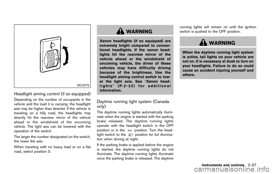
Headlight aiming control (if so equipped)
Depending on the number of occupants in the
vehicle and the load it is carrying, the headlight
axis may be higher than desired. If the vehicle is
traveling on a hilly road, the headlights may
directly hit the rearview mirror of the vehicle
ahead or the windshield of the oncoming
vehicle. The light axis can be lowered with the
operation of the switch.
The larger the number designated on the switch,
the lower the axis.
When traveling with no heavy load or on a flat
road, select position 0.
WARNING
Xenon headlights (if so equipped) are
extremely bright compared to conven-
tional headlights. If the xenon head-
lights hit the rearview mirror of the
vehicle ahead or the windshield of
oncoming vehicle, the driver of these
vehicles may have difficulty driving
because of the brightness. Use the
headlight aiming control switch to low-
er the light axis. See“Xenon head-
lights” (P.2-33) for additional
information.
Daytime running light system (Canada
only)
The daytime running lights automatically illumi-
nate when the engine is started with the parking
brake released. The daytime running lights
operate with the headlight switch in the OFF
position or in the
position. Turn the head-
light switch to theposition for full illumina-
tion when driving at night.
If the parking brake is applied before the engine
is started, the daytime running lights do not
illuminate. The daytime running lights illuminate
once the parking brake is released. The daytime running lights will remain on until the ignition
switch is pushed to the OFF position.
WARNING
When the daytime running light system
is active, tail lights on your vehicle are
not on. It is necessary at dusk to turn on
your headlights. Failure to do so could
cause an accident injuring yourself and
others.
Instruments and controls2-37
Page 128 of 520
SSD1179
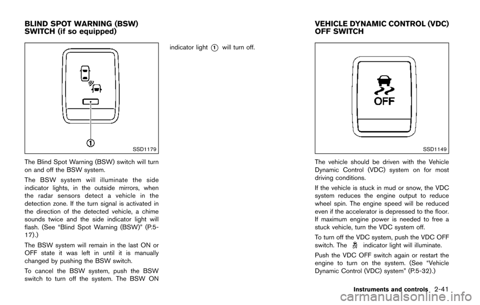
The Blind Spot Warning (BSW) switch will turn
on and off the BSW system.
The BSW system will illuminate the side
indicator lights, in the outside mirrors, when
the radar sensors detect a vehicle in the
detection zone. If the turn signal is activated in
the direction of the detected vehicle, a chime
sounds twice and the side indicator light will
flash. (See “Blind Spot Warning (BSW)” (P.5-
17) .)
The BSW system will remain in the last ON or
OFF state it was left in until it is manually
changed by pushing the BSW switch.
To cancel the BSW system, push the BSW
switch to turn off the system. The BSW ONindicator light
*1will turn off.
SSD1149
The vehicle should be driven with the Vehicle
Dynamic Control (VDC) system on for most
driving conditions.
If the vehicle is stuck in mud or snow, the VDC
system reduces the engine output to reduce
wheel spin. The engine speed will be reduced
even if the accelerator is depressed to the floor.
If maximum engine power is needed to free a
stuck vehicle, turn the VDC system off.
To turn off the VDC system, push the VDC OFF
switch. The
indicator light will illuminate.
Push the VDC OFF switch again or restart the
engine to turn on the system. (See “Vehicle
Dynamic Control (VDC) system” (P.5-32) .)
Instruments and controls2-41
BLIND SPOT WARNING (BSW)
SWITCH (if so equipped) VEHICLE DYNAMIC CONTROL (VDC)
OFF SWITCH
Page 146 of 520
— remain on while the door is opened.When the door is closed, the lights go
off.
OFF position
When the switch is in the OFF position*3, the
lights will not illuminate, regardless of the
condition.
CAUTION
Do not use for extended periods of time
with the engine stopped. This could
result in a discharged battery.
SIC4747
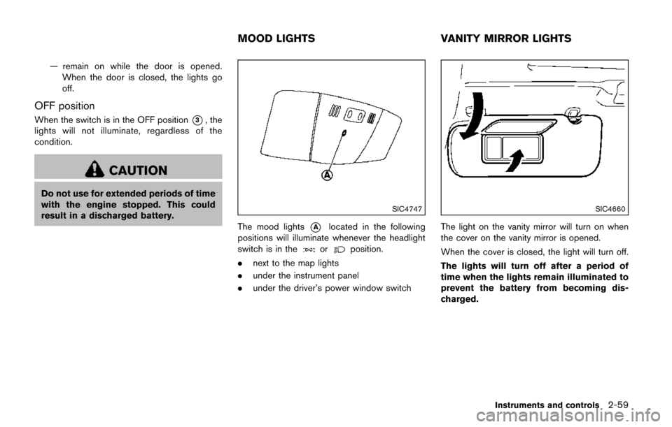
The mood lights*Alocated in the following
positions will illuminate whenever the headlight
switch is in the
orposition.
. next to the map lights
. under the instrument panel
. under the driver’s power window switch
SIC4660
The light on the vanity mirror will turn on when
the cover on the vanity mirror is opened.
When the cover is closed, the light will turn off.
The lights will turn off after a period of
time when the lights remain illuminated to
prevent the battery from becoming dis-
charged.
Instruments and controls2-59
MOOD LIGHTS VANITY MIRROR LIGHTS
Page 238 of 520
SAA3596
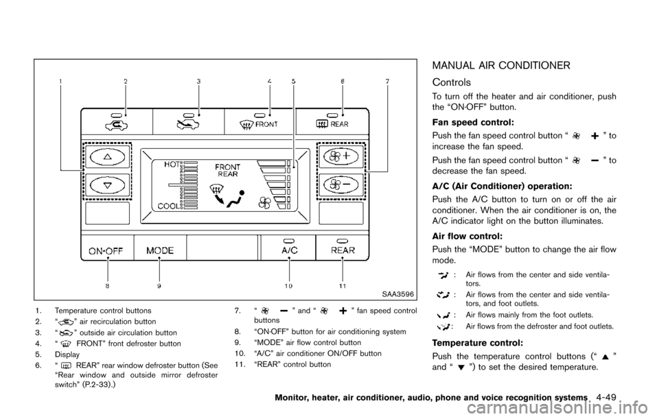
1. Temperature control buttons
2. “” air recirculation button
3. “” outside air circulation button
4. “FRONT” front defroster button
5. Display
6. “
REAR” rear window defroster button (See
“Rear window and outside mirror defroster
switch” (P.2-33) .) 7. “
” and “” fan speed control
buttons
8. “ON·OFF” button for air conditioning system
9. “MODE” air flow control button
10. “A/C” air conditioner ON/OFF button
11. “REAR” control button
MANUAL AIR CONDITIONER
Controls
To turn off the heater and air conditioner, push
the “ON·OFF” button.
Fan speed control:
Push the fan speed control button “
”to
increase the fan speed.
Push the fan speed control button “
”to
decrease the fan speed.
A/C (Air Conditioner) operation:
Push the A/C button to turn on or off the air
conditioner. When the air conditioner is on, the
A/C indicator light on the button illuminates.
Air flow control:
Push the “MODE” button to change the air flow
mode.
: Air flows from the center and side ventila- tors.
: Air flows from the center and side ventila-tors, and foot outlets.
: Air flows mainly from the foot outlets.
: Air flows from the defroster and foot outlets.
Temperature control:
Push the temperature control buttons (“
”
and “”) to set the desired temperature.
Monitor, heater, air conditioner, audio, phone and voice recognition systems4-49