2017 NISSAN QUEST fuel
[x] Cancel search: fuelPage 163 of 520
3-12Pre-driving checks and adjustments
The power sliding door system can be operated
when all of following conditions are satisfied.
.The vehicle is stopped.
. Battery voltage is normal.
. The sliding door is unlocked.
. The fuel-filler door is closed (for driver’s side
only) .
When the ignition switch is in the "ON" position,
the system can be operated in the above and
following conditions.
. Shift lever is set in the “P” (Park) position.
If the conditions are interrupted when the power
sliding door is being operated, the operation
could be stopped. In this case, meet the
conditions above and the power sliding door
operation will return to normal.
You can also switch the power liftgate between
power and manual operation using the power
door main switch. (See “Liftgate” (P.3-26).)
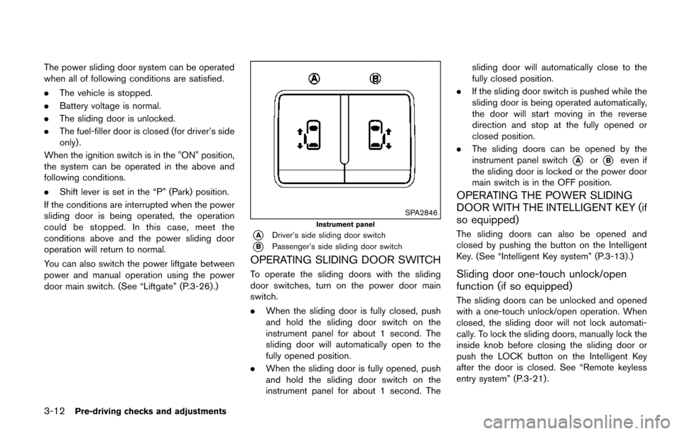
SPA2846
Instrument panel
*ADriver’s side sliding door switch
*BPassenger’s side sliding door switch
OPERATING SLIDING DOOR SWITCH
To operate the sliding doors with the sliding
door switches, turn on the power door main
switch.
. When the sliding door is fully closed, push
and hold the sliding door switch on the
instrument panel for about 1 second. The
sliding door will automatically open to the
fully opened position.
. When the sliding door is fully opened, push
and hold the sliding door switch on the
instrument panel for about 1 second. The sliding door will automatically close to the
fully closed position.
. If the sliding door switch is pushed while the
sliding door is being operated automatically,
the door will start moving in the reverse
direction and stop at the fully opened or
closed position.
. The sliding doors can be opened by the
instrument panel switch
*Aor*Beven if
the sliding door is locked or the power door
main switch is in the OFF position.
OPERATING THE POWER SLIDING
DOOR WITH THE INTELLIGENT KEY (if
so equipped)
The sliding doors can also be opened and
closed by pushing the button on the Intelligent
Key. (See “Intelligent Key system” (P.3-13).)
Sliding door one-touch unlock/open
function (if so equipped)
The sliding doors can be unlocked and opened
with a one-touch unlock/open operation. When
closed, the sliding door will not lock automati-
cally. To lock the sliding doors, manually lock the
inside knob before closing the sliding door or
push the LOCK button on the Intelligent Key
after the door is closed. See “Remote keyless
entry system” (P.3-21) .
Page 181 of 520
3-30Pre-driving checks and adjustments
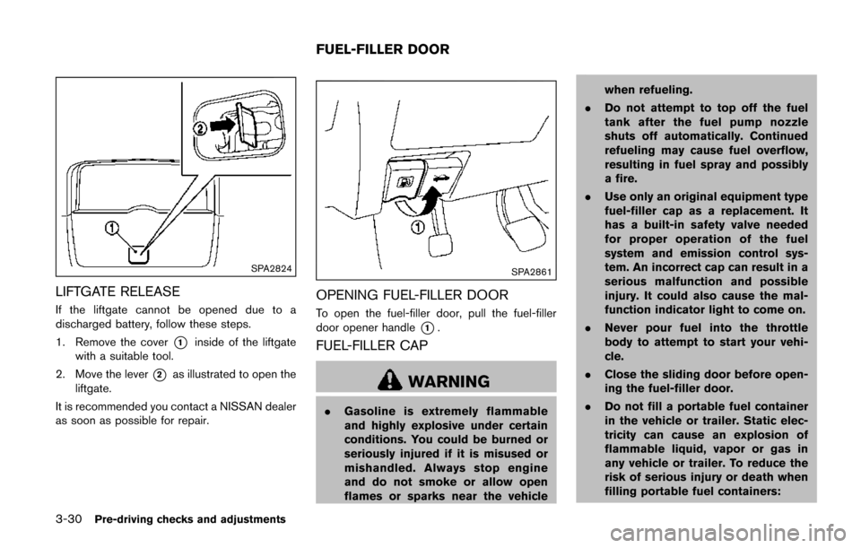
SPA2824
LIFTGATE RELEASE
If the liftgate cannot be opened due to a
discharged battery, follow these steps.
1. Remove the cover
*1inside of the liftgate
with a suitable tool.
2. Move the lever
*2as illustrated to open the
liftgate.
It is recommended you contact a NISSAN dealer
as soon as possible for repair.
SPA2861
OPENING FUEL-FILLER DOOR
To open the fuel-filler door, pull the fuel-filler
door opener handle
*1.
FUEL-FILLER CAP
WARNING
. Gasoline is extremely flammable
and highly explosive under certain
conditions. You could be burned or
seriously injured if it is misused or
mishandled. Always stop engine
and do not smoke or allow open
flames or sparks near the vehicle when refueling.
. Do not attempt to top off the fuel
tank after the fuel pump nozzle
shuts off automatically. Continued
refueling may cause fuel overflow,
resulting in fuel spray and possibly
a fire.
. Use only an original equipment type
fuel-filler cap as a replacement. It
has a built-in safety valve needed
for proper operation of the fuel
system and emission control sys-
tem. An incorrect cap can result in a
serious malfunction and possible
injury. It could also cause the mal-
function indicator light to come on.
. Never pour fuel into the throttle
body to attempt to start your vehi-
cle.
. Close the sliding door before open-
ing the fuel-filler door.
. Do not fill a portable fuel container
in the vehicle or trailer. Static elec-
tricity can cause an explosion of
flammable liquid, vapor or gas in
any vehicle or trailer. To reduce the
risk of serious injury or death when
filling portable fuel containers:
FUEL-FILLER DOOR
Page 182 of 520
— Always place the container onthe ground when filling.
— Do not use electronic devices when filling.
— Keep the pump nozzle in contact with the container while you are
filling it.
— Use only approved portable fuel containers for flammable liquid.
CAUTION
. If fuel is spilled on the vehicle body,
flush it away with water to avoid
paint damage.
. Insert the cap straight into the fuel-
filler tube, then tighten until the
fuel-filler cap clicks. Failure to tight-
en the fuel-filler cap properly may
cause the
malfunction indicator
light (MIL) to illuminate. If the
light illuminates because the fuel-
filler cap is loose or missing, tighten
or install the cap and continue to
drive the vehicle. The
light
should turn off after a few driving
trips. If the
light does not turn off after a few driving trips, have the
vehicle inspected. It is recom-
mended you visit a NISSAN dealer
for this service.
For additional information, see
“Malfunction Indicator Light (MIL)”
(P.2-17) .
. The LOOSE FUEL CAP warning will
appear if the fuel-filler cap is not
properly tightened. It may take a few
driving trips for the message to be
displayed. Failure to tighten the
fuel-filler cap properly after the
LOOSE FUEL CAP warning appears
may cause the
Malfunction
Indicator Light (MIL) to illuminate.
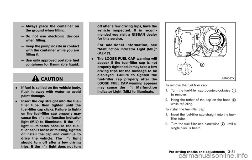
JVP0067X
To remove the fuel-filler cap:
1. Turn the fuel-filler cap counterclockwise
*1
to remove.
2. Hang the tether of the cap on the hook
*3
while refueling.
To install the fuel-filler cap:
1. Insert the fuel-filler cap straight into the fuel- filler tube.
2. Turn the fuel-filler cap clockwise
*2until a
single click is heard.
Pre-driving checks and adjustments3-31
Page 183 of 520
3-32Pre-driving checks and adjustments
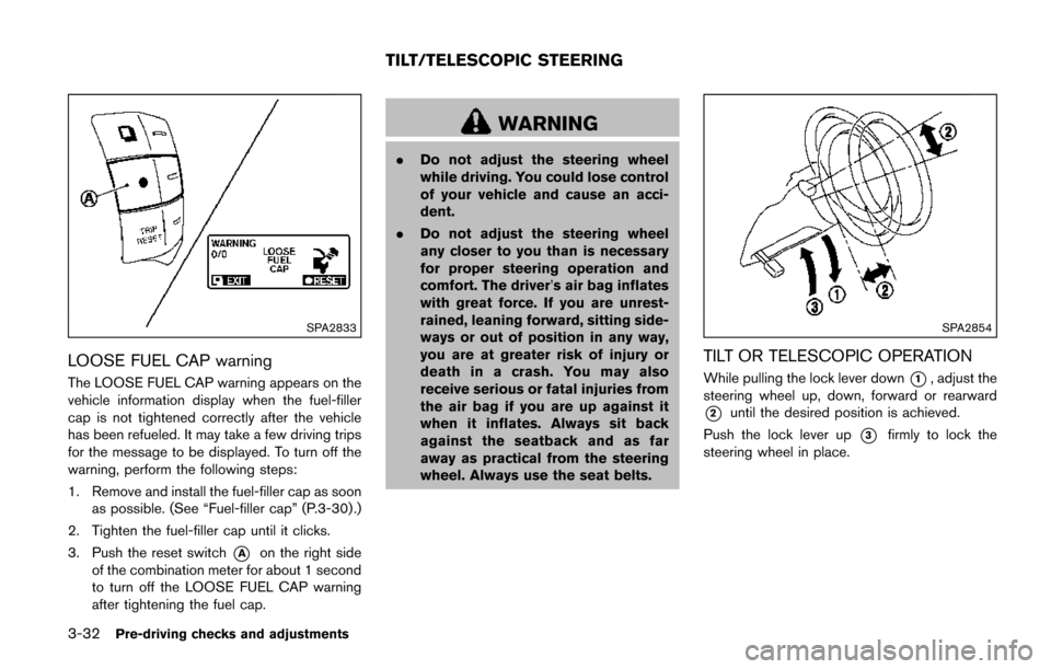
SPA2833
LOOSE FUEL CAP warning
The LOOSE FUEL CAP warning appears on the
vehicle information display when the fuel-filler
cap is not tightened correctly after the vehicle
has been refueled. It may take a few driving trips
for the message to be displayed. To turn off the
warning, perform the following steps:
1. Remove and install the fuel-filler cap as soonas possible. (See “Fuel-filler cap” (P.3-30) .)
2. Tighten the fuel-filler cap until it clicks.
3. Push the reset switch
*Aon the right side
of the combination meter for about 1 second
to turn off the LOOSE FUEL CAP warning
after tightening the fuel cap.
WARNING
. Do not adjust the steering wheel
while driving. You could lose control
of your vehicle and cause an acci-
dent.
. Do not adjust the steering wheel
any closer to you than is necessary
for proper steering operation and
comfort. The driver’s air bag inflates
with great force. If you are unrest-
rained, leaning forward, sitting side-
ways or out of position in any way,
you are at greater risk of injury or
death in a crash. You may also
receive serious or fatal injuries from
the air bag if you are up against it
when it inflates. Always sit back
against the seatback and as far
away as practical from the steering
wheel. Always use the seat belts.
SPA2854
TILT OR TELESCOPIC OPERATION
While pulling the lock lever down*1, adjust the
steering wheel up, down, forward or rearward
*2until the desired position is achieved.
Push the lock lever up
*3firmly to lock the
steering wheel in place.
TILT/TELESCOPIC STEERING
Page 199 of 520
4-10Monitor, heater, air conditioner, audio, phone and voice recognition systems
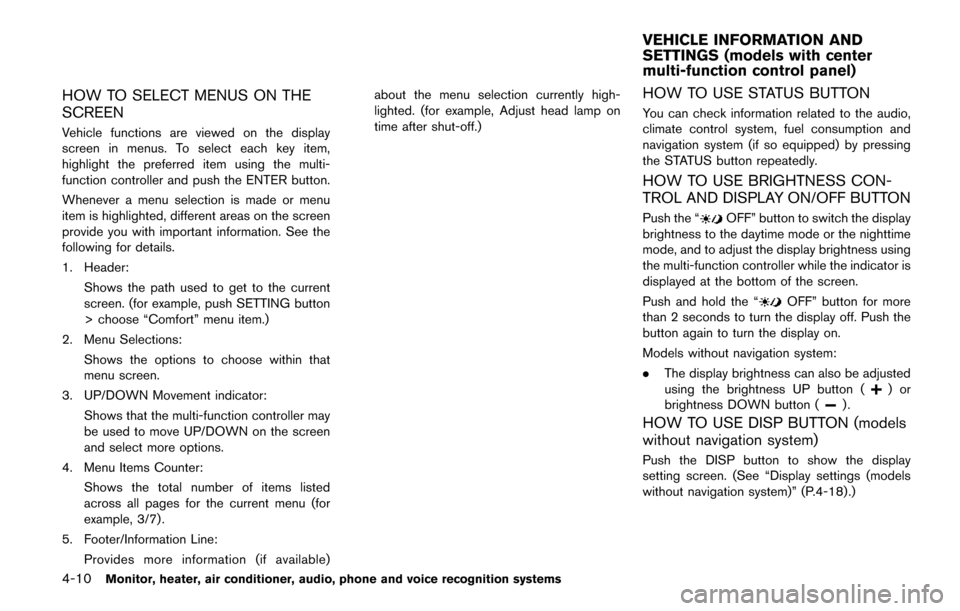
HOW TO SELECT MENUS ON THE
SCREEN
Vehicle functions are viewed on the display
screen in menus. To select each key item,
highlight the preferred item using the multi-
function controller and push the ENTER button.
Whenever a menu selection is made or menu
item is highlighted, different areas on the screen
provide you with important information. See the
following for details.
1. Header:Shows the path used to get to the current
screen. (for example, push SETTING button
> choose “Comfort” menu item.)
2. Menu Selections: Shows the options to choose within that
menu screen.
3. UP/DOWN Movement indicator: Shows that the multi-function controller may
be used to move UP/DOWN on the screen
and select more options.
4. Menu Items Counter: Shows the total number of items listed
across all pages for the current menu (for
example, 3/7) .
5. Footer/Information Line: Provides more information (if available) about the menu selection currently high-
lighted. (for example, Adjust head lamp on
time after shut-off.)
HOW TO USE STATUS BUTTON
You can check information related to the audio,
climate control system, fuel consumption and
navigation system (if so equipped) by pressing
the STATUS button repeatedly.
HOW TO USE BRIGHTNESS CON-
TROL AND DISPLAY ON/OFF BUTTON
Push the “OFF” button to switch the display
brightness to the daytime mode or the nighttime
mode, and to adjust the display brightness using
the multi-function controller while the indicator is
displayed at the bottom of the screen.
Push and hold the “
OFF” button for more
than 2 seconds to turn the display off. Push the
button again to turn the display on.
Models without navigation system:
. The display brightness can also be adjusted
using the brightness UP button (
)or
brightness DOWN button ().
HOW TO USE DISP BUTTON (models
without navigation system)
Push the DISP button to show the display
setting screen. (See “Display settings (models
without navigation system)” (P.4-18).)
VEHICLE INFORMATION AND
SETTINGS (models with center
multi-function control panel)
Page 200 of 520
HOW TO USE ECON BUTTON (models
without navigation system)
Push the “ECON” button to show fuel
economy information. (See “How to use INFO
button” (P.4-11).)
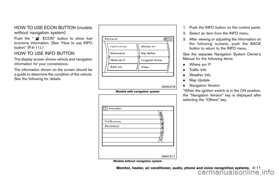
HOW TO USE INFO BUTTON
The display screen shows vehicle and navigation
information for your convenience.
The information shown on the screen should be
a guide to determine the condition of the vehicle.
See the following for details.
SAA2478
Models with navigation system
SAA1511Models without navigation system
1. Push the INFO button on the control panel.
2. Select an item from the INFO menu.
3. After viewing or adjusting the information on the following screens, push the BACK
button to return to the INFO menu.
See the separate Navigation System Owner’s
Manual for the following items:
. Where am I?
. Traffic Info
. Weather Info
. Map Update
. Navigation Version
*When the ignition switch is in the ON position,
the “Navigation Version” key is displayed after
selecting the “Others” key.
Monitor, heater, air conditioner, audio, phone and voice recognition systems4-11
Page 201 of 520
4-12Monitor, heater, air conditioner, audio, phone and voice recognition systems
JVH0995X
SAA2480Models with navigation system
JVH0996X
JVH0181MModels without navigation system
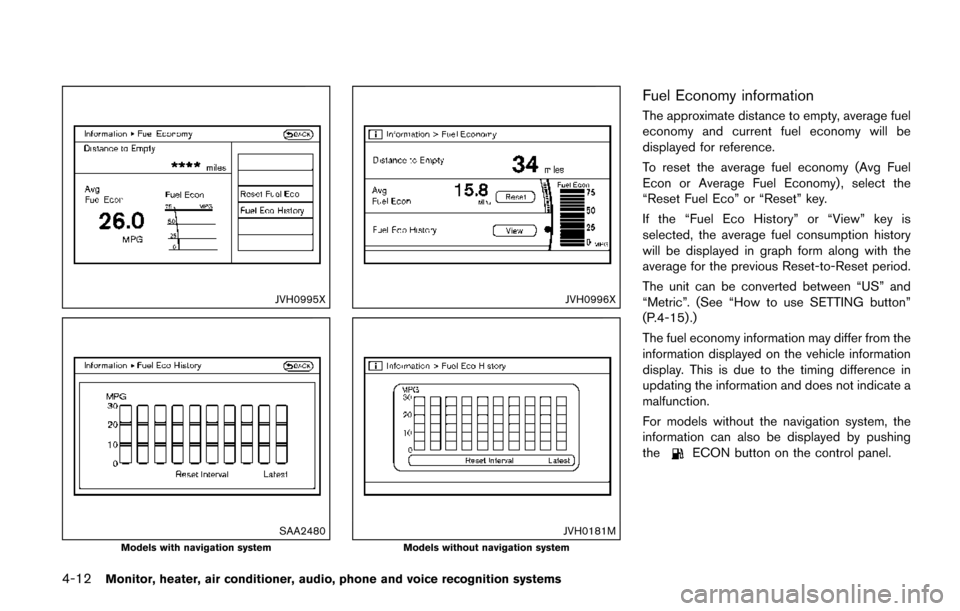
Fuel Economy information
The approximate distance to empty, average fuel
economy and current fuel economy will be
displayed for reference.
To reset the average fuel economy (Avg Fuel
Econ or Average Fuel Economy) , select the
“Reset Fuel Eco” or “Reset” key.
If the “Fuel Eco History” or “View” key is
selected, the average fuel consumption history
will be displayed in graph form along with the
average for the previous Reset-to-Reset period.
The unit can be converted between “US” and
“Metric”. (See “How to use SETTING button”
(P.4-15) .)
The fuel economy information may differ from the
information displayed on the vehicle information
display. This is due to the timing difference in
updating the information and does not indicate a
malfunction.
For models without the navigation system, the
information can also be displayed by pushing
the
ECON button on the control panel.
Page 219 of 520
4-30Monitor, heater, air conditioner, audio, phone and voice recognition systems
REARVIEW MONITOR SYSTEM LIM-
ITATIONS
WARNING
Listed below are the system limitations
for RearView Monitor. Failure to oper-
ate the vehicle in accordance with these
system limitations could result in ser-
ious injury or death.
.The system cannot completely elim-
inate blind spots and may not show
every object.
. Underneath the bumper and the
corner areas of the bumper cannot
be viewed on the RearView Monitor
because of its monitoring range
limitation. The system will not show
small objects below the bumper,
and may not show objects close to
the bumper or on the ground.
. Objects viewed in the RearView
Monitor differ from actual distance
because a wide-angle lens is used.
. Objects in the RearView Monitor
will appear visually opposite com-
pared to when viewed in the rear
view and outside mirrors. .
Use the displayed lines as a refer-
ence. The lines are highly affected
by the number of occupants, fuel
level, vehicle position, road condi-
tions and road grade.
. Make sure that the liftgate is se-
curely closed when backing up.
. Do not put anything on the rearview
camera. The rearview camera is
installed above the license plate.
. When washing the vehicle with
high-pressure water, be sure not to
spray it around the camera. Other-
wise, water may enter the camera
unit causing water condensation on
the lens, a malfunction, fire or an
electric shock.
. Do not strike the camera. It is a
precision instrument. Otherwise, it
may malfunction or cause damage
resulting in a fire or an electric
shock.
The following are operating limitations and do
not represent a system malfunction:
. When the temperature is extremely high or
low, the screen may not clearly display
objects. .
When strong light is directly coming on the
camera, objects may not be displayed
clearly.
. Vertical lines may be seen in objects on the
screen. This is due to strong reflected light
from the bumper.
. The screen may flicker under fluorescent
light.
. The colors of objects on the RearView
Monitor may differ somewhat from the actual
color of objects.
. Objects on the monitor may not be clear in a
dark environment.
. If dirt, rain or snow accumulates on the
camera, the RearView Monitor may not
display objects clearly. Clean the camera.
. Do not use wax on the camera window.
Wipe off any wax with a clean cloth
dampened with mild detergent diluted with
water.