Page 8 of 466
Table of
ContentsIllustrated table of contents
Safety—Seats, seat belts and supplemental restraint system
Instruments and controls
Pre-driving checks and adjustments
Display screen, heater, air conditioner, audio and phone systems
Starting and driving
In case of emergency
Appearance and care
Do-it-yourself
Maintenance and schedules
Technical and consumer information
Index
0
1
2
3
4
5
6
7
8
9
10
11
Page 15 of 466
1. Vent (P. 4-25)
2. Headlight/fog light (if so equipped)/turnsignal switch (P. 2-33)
3. Supplemental air bag (P. 1-48)
4. Meters and gauges (P. 2-3) Warning and indicator lights (P. 2-7)
Vehicle information display (P. 2-15)
5. Wiper and washer switch (P. 2-30) Rear window wiper and washer switch
(P. 2-30)
6. Audio system/Center display controls
(P. 4-38)
7. Hazard warning flasher switch (P. 6-2)
8. Center display (P. 4-38) Navigation display* (if so equipped)
9. Front passenger supplemental air bag
(P. 1-48)
10. Glove box (P. 2-46)
11. Front passenger air bag status light
(P. 1-48)
12. Power outlet (P. 2-42)
13. Climate controlled seat switch
(if so equipped) (P. 2-37)
Heated seat switch (if so equipped)
(P. 2-38)
14. Heater and air conditioning controls
(P. 4-26)
LII2374
INSTRUMENT PANEL
0-6Illustrated table of contents
Page 86 of 466

WARNING
Do not use a rear-facing child restraint on
a seat protected by an air bag in front of it.
If the air bag deploys, it may cause serious
injury or death.
SUPPLEMENTAL AIR BAG
WARNING LIGHT
The supplemental air bag warning light,
displaying
in the instrument panel, moni-
tors the circuits for the air bag systems, preten-
sioner(s) and all related wiring.
When the ignition switch is placed in the ON
position, the supplemental air bag warning light
illuminates for about 7 seconds and then turns
off. This means the system is operational. If any of the following conditions occur, the front
air bag, side air bag, curtain air bag, knee air bag
and pretensioner systems need servicing:
● The supplemental air bag warning light re-
mains on after approximately 7 seconds.
● The supplemental air bag warning light
flashes intermittently.
● The supplemental air bag warning light does
not come on at all.
Under these conditions, the front air bag, side air
bag, curtain air bag, knee air bag or pretensioner
systems may not operate properly. They must be
checked and repaired. It is recommended that
you visit a NISSAN dealer for this service.
WARNING
If the supplemental air bag warning light
is on, it could mean that the front air bag,
side air bag, curtain air bag, knee air bag
and/or pretensioner systems will not op-
erate in an accident. To help avoid injury to
yourself or others, have your vehicle
checked as soon as possible. It is recom-
mended that you visit a NISSAN dealer for
this service.
LRS0100
Safety—Seats, seat belts and supplemental restraint system1-67
Page 89 of 466

2 Instruments and controls
Instrument panel...................................2-2
Meters and gauges ................................2-3
Speedometer and odometer .....................2-4
Tachometer ....................................2-5
Engine coolant temperature gauge ...............2-5
Fuel gauge ....................................2-6
Warning lights, indicator lights and audible
reminders .........................................2-7
Checking lights ................................2-7
Warning lights .................................2-7
Indicator lights ................................ 2-12
Audible reminders ............................. 2-14
Vehicle information display ......................... 2-15
How to use the vehicle information display .......2-15
Startup display ................................ 2-16
Settings ...................................... 2-16
Vehicle information display warnings and
indicators ..................................... 2-23
Security systems ................................. 2-27
Vehicle security system ......................... 2-27
NISSAN vehicle immobilizer system .............2-28
Wiper and washer switch ......................... 2-30
Switch operation .............................. 2-30Rear switch operation
.......................... 2-31
Rear window and outside mirror (if so equipped)
defroster switch .................................. 2-32
Headlight and turn signal switch ....................2-33
Headlight control switch ........................ 2-33
Daytime running light system ....................2-35
Instrument brightness control ...................2-35
Turn signal switch ............................. 2-36
Fog light switch (if so equipped) ................2-36
Horn ............................................ 2-37
Climate controlled seat switches (if so equipped) ....2-37
Heated seat switches (if so equipped) ..............2-38
Heated rear seat switches (if so equipped) ..........2-39
Heated steering wheel switch (if so equipped) .......2-40
Vehicle Dynamic Control (VDC) off switch ...........2-41
E-call (SOS) switch (if so equipped) ................2-42
P
ower outlets .................................... 2-42
12v outlets ................................... 2-42
Extended storage switch .......................... 2-43
Storage ......................................... 2-44
Front-door pockets ............................ 2-44
Console side pockets (if so equipped) ...........2-45
Seatback pockets ............................. 2-45
Page 91 of 466
1. Vent (P. 4-25)
2. Headlight/fog light (if so equipped)/turnsignal switch (P. 2-33)
3. Supplemental air bag (P. 1-48)
4. Meters and gauges (P. 2-3) Warning and indicator lights (P. 2-7)
Vehicle information display (P. 2-15)
5. Wiper and washer switch (P. 2-30) Rear window wiper and washer switch
(P. 2-30)
6. Audio system/Center display controls
(P. 4-38)
7. Hazard warning flasher switch (P. 6-2)
8. Center display (P. 4-38) Navigation display* (if so equipped)
9. Front passenger supplemental air bag
(P. 1-48)
10. Glove box (P. 2-46)
11. Front passenger air bag status light
(P. 1-48)
12. Power outlet (P. 2-42)
13. Climate controlled seat switch
(if so equipped) (P. 2-37)
Heated seat switch (if so equipped)
(P. 2-38)
14. Heater and air conditioning controls
(P. 4-26)
LII2374
INSTRUMENT PANEL
2-2Instruments and controls
Page 92 of 466

16. Push-button ignition switch (P. 5-11)
17. Cruise control switches(if so equipped) (P. 5-39)
Intelligent Cruise Control (ICC)
switches (if so equipped) (P. 5-41)
18. Drive")
15. Shift lever (P. 5-16)
16. Push-button ignition switch (P. 5-11)
17. Cruise control switches(if so equipped) (P. 5-39)
Intelligent Cruise Control (ICC)
switches (if so equipped) (P. 5-41)
18. Driver supplemental knee air bag
(P. 1-48)
19. Bluetooth® Hands-Free Phone
System/Audio control switches
(P. 4-54)
20. Hood release (P. 3-21) Fuel door release (P. 3-27)
Powered rear seatback switch (P. 1-2)
21. Fuse box (P. 8-18)
22. Power liftgate main switch
(if so equipped) (P. 3-21)
Heated steering wheel switch
(if so equipped) (P. 2-40)
Vehicle Dynamic Control (VDC) OFF
switch (P. 2-41)
23. Instrument brightness control (P. 2-33) Twin trip odometer reset switch (P. 2-3)
*: Refer to the separate Navigation System Own-
er’s Manual (if so equipped) .
Refer to the page number indicated in pa-
rentheses for operating details.
1. Tachometer
2. Warning and indicator lights
3. Vehicle information displayOdometer
Twin Trip Odometer 4. Speedometer
5. Fuel gauge
6. Engine coolant temperature gauge
LIC2920
METERS AND GAUGES
Instruments and controls2-3
Page 93 of 466
SPEEDOMETER AND ODOMETER
This vehicle is equipped with a speedometer and
odometer. The speedometer is located on the
right side of the meter cluster. The odometer is
located within the vehicle information display.
Speedometer
The speedometer indicates vehicle speed.
Odometer/Twin trip odometer
The odometer and the twin trip odometer�1are
displayed below the vehicle information display
when the ignition switch is placed in the ON
position.
The odometer records the total distance the ve-
hicle has been driven.
The twin trip odometer records the distance of
individual trips.
LIC2218LIC2921
2-4Instruments and controls
Page 94 of 466
Changing the display
Push the TRIP RESET
�2switch on the left side
of the instrument panel to change the display as
follows:
Trip
→ Trip→Trip
Resetting the trip odometer
Pushing the TRIP RESET switch
�2for more
than 1 second resets the currently displayed trip
odometer to zero.
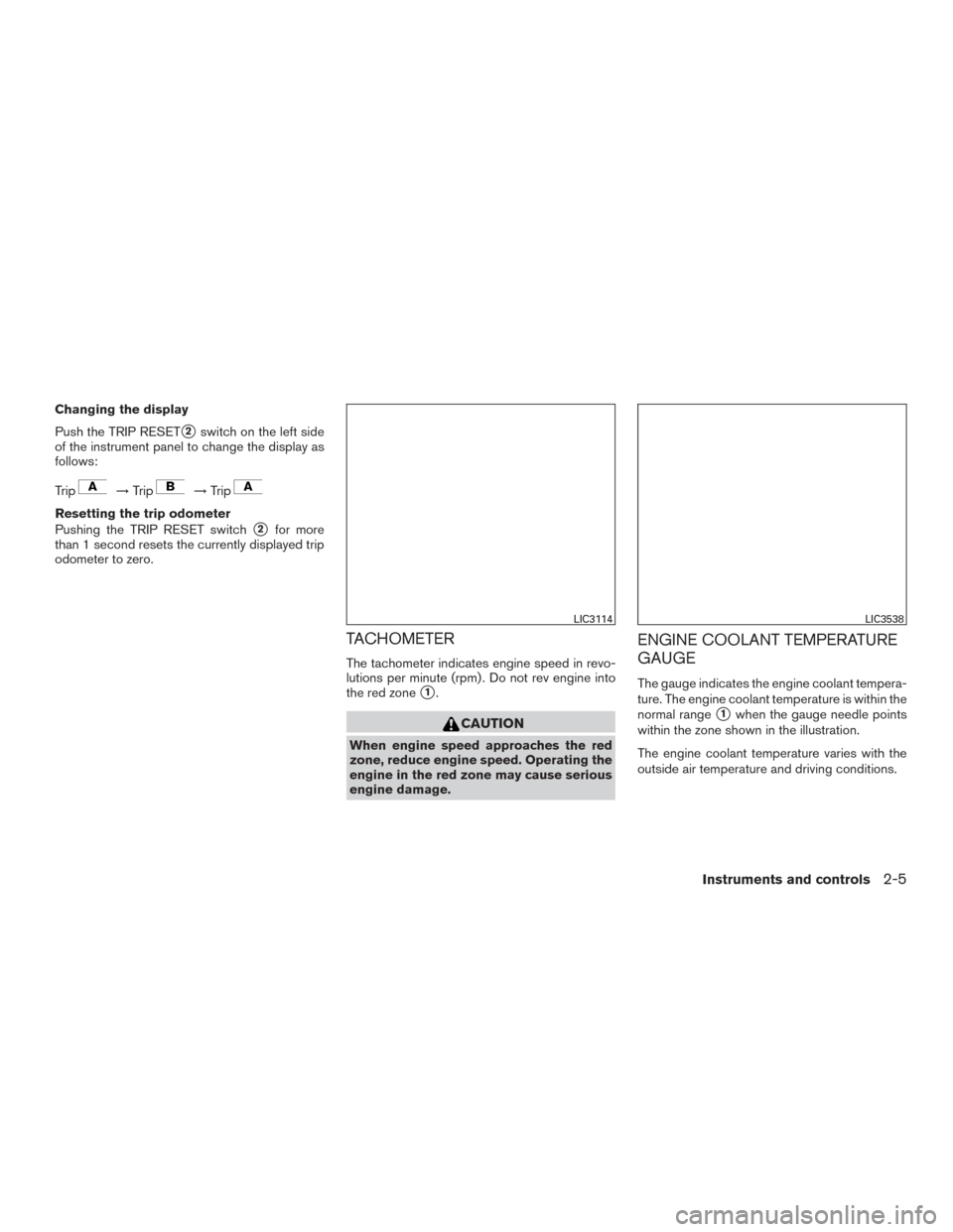
TACHOMETER
The tachometer indicates engine speed in revo-
lutions per minute (rpm) . Do not rev engine into
the red zone
�1.
CAUTION
When engine speed approaches the red
zone, reduce engine speed. Operating the
engine in the red zone may cause serious
engine damage.
ENGINE COOLANT TEMPERATURE
GAUGE
The gauge indicates the engine coolant tempera-
ture. The engine coolant temperature is within the
normal range
�1when the gauge needle points
within the zone shown in the illustration.
The engine coolant temperature varies with the
outside air temperature and driving conditions.
LIC3114LIC3538
Instruments and controls2-5


2. Headlight/fog light (if so equipped)/turnsignal switch (P. 2-33)
3. Supplemental air bag (P. 1-48)
4. Meters and gauges (P. 2-3) Warning and indicator lights (P. 2-7)
Vehicle info")

2. Headlight/fog light (if so equipped)/turnsignal switch (P. 2-33)
3. Supplemental air bag (P. 1-48)
4. Meters and gauges (P. 2-3) Warning and indicator lights (P. 2-7)
Vehicle info")