2017 NISSAN MURANO ECO mode
[x] Cancel search: ECO modePage 107 of 466
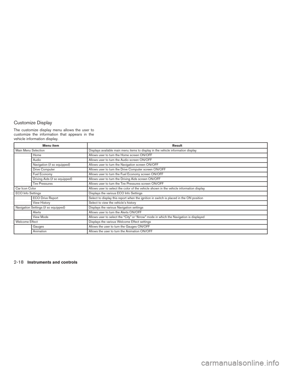
Customize Display
The customize display menu allows the user to
customize the information that appears in the
vehicle information display.
Menu itemResult
Main Menu Selection Displays available main menu items to display in the vehicle information display
Home Allows user to turn the Home screen ON/OFF
Audio Allows user to turn the Audio screen ON/OFF
Navigation (if so equipped) Allows user to turn the Navigation screen ON/OFF
Drive Computer Allows user to turn the Drive Computer screen ON/OFF
Fuel Economy Allows user to turn the Fuel Economy screen ON/OFF
Driving Aids (if so equipped) Allows user to turn the Driving Aids screen ON/OFF
Tire Pressures Allows user to turn the Tire Pressures screen ON/OFF
Car Icon Color Allows user to select the color of the vehicle shown in the vehicle information display
ECO Info Settings Displays the various ECO Info Settings
ECO Drive Report Select to display this report when the ignition in switch is placed in the ON position
View History Select to view the vehicle’s history
Navigation Settings (if so equipped) Displays the various Navigation settings
Alerts Allows user to turn the Alerts ON/OFF
View Mode Allows user to select the “City” or “Arrow” mode in which the Navigation is displayed
Welcome Effect Displays the various Welcome Effect settings
Gauges Allows the user to turn the Gauges ON/OFF
Animation Allows the user to turn the Animation ON/OFF
2-18Instruments and controls
Page 114 of 466
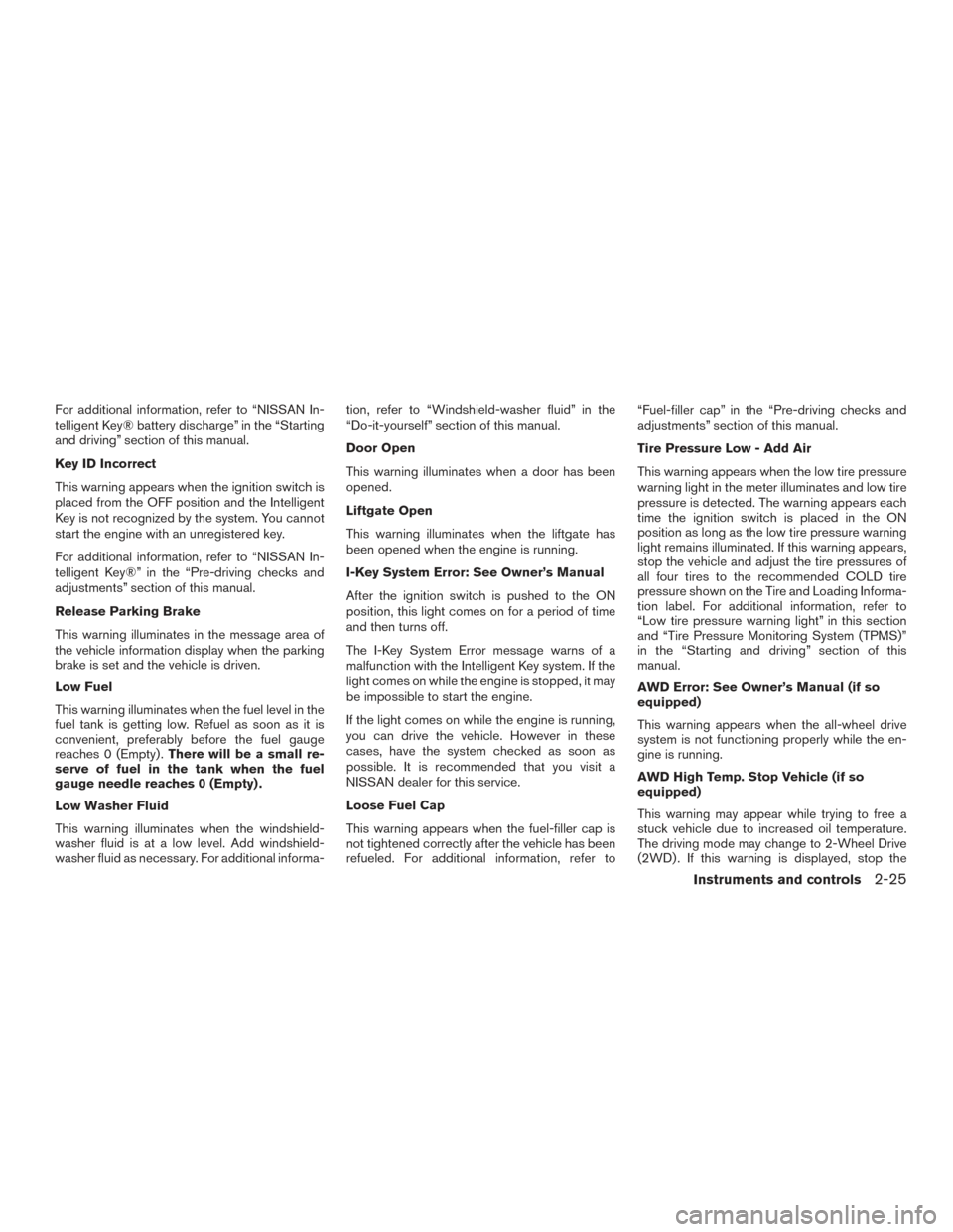
For additional information, refer to “NISSAN In-
telligent Key® battery discharge” in the “Starting
and driving” section of this manual.
Key ID Incorrect
This warning appears when the ignition switch is
placed from the OFF position and the Intelligent
Key is not recognized by the system. You cannot
start the engine with an unregistered key.
For additional information, refer to “NISSAN In-
telligent Key®” in the “Pre-driving checks and
adjustments” section of this manual.
Release Parking Brake
This warning illuminates in the message area of
the vehicle information display when the parking
brake is set and the vehicle is driven.
Low Fuel
This warning illuminates when the fuel level in the
fuel tank is getting low. Refuel as soon as it is
convenient, preferably before the fuel gauge
reaches 0 (Empty) .There will be a small re-
serve of fuel in the tank when the fuel
gauge needle reaches 0 (Empty) .
Low Washer Fluid
This warning illuminates when the windshield-
washer fluid is at a low level. Add windshield-
washer fluid as necessary. For additional informa- tion, refer to “Windshield-washer fluid” in the
“Do-it-yourself” section of this manual.
Door Open
This warning illuminates when a door has been
opened.
Liftgate Open
This warning illuminates when the liftgate has
been opened when the engine is running.
I-Key System Error: See Owner’s Manual
After the ignition switch is pushed to the ON
position, this light comes on for a period of time
and then turns off.
The I-Key System Error message warns of a
malfunction with the Intelligent Key system. If the
light comes on while the engine is stopped, it may
be impossible to start the engine.
If the light comes on while the engine is running,
you can drive the vehicle. However in these
cases, have the system checked as soon as
possible. It is recommended that you visit a
NISSAN dealer for this service.
Loose Fuel Cap
This warning appears when the fuel-filler cap is
not tightened correctly after the vehicle has been
refueled. For additional information, refer to“Fuel-filler cap” in the “Pre-driving checks and
adjustments” section of this manual.
Tire Pressure Low - Add Air
This warning appears when the low tire pressure
warning light in the meter illuminates and low tire
pressure is detected. The warning appears each
time the ignition switch is placed in the ON
position as long as the low tire pressure warning
light remains illuminated. If this warning appears,
stop the vehicle and adjust the tire pressures of
all four tires to the recommended COLD tire
pressure shown on the Tire and Loading Informa-
tion label. For additional information, refer to
“Low tire pressure warning light” in this section
and “Tire Pressure Monitoring System (TPMS)”
in the “Starting and driving” section of this
manual.
AWD Error: See Owner’s Manual (if so
equipped)
This warning appears when the all-wheel drive
system is not functioning properly while the en-
gine is running.
AWD High Temp. Stop Vehicle (if so
equipped)
This warning may appear while trying to free a
stuck vehicle due to increased oil temperature.
The driving mode may change to 2-Wheel Drive
(2WD) . If this warning is displayed, stop the
Instruments and controls2-25
Page 115 of 466
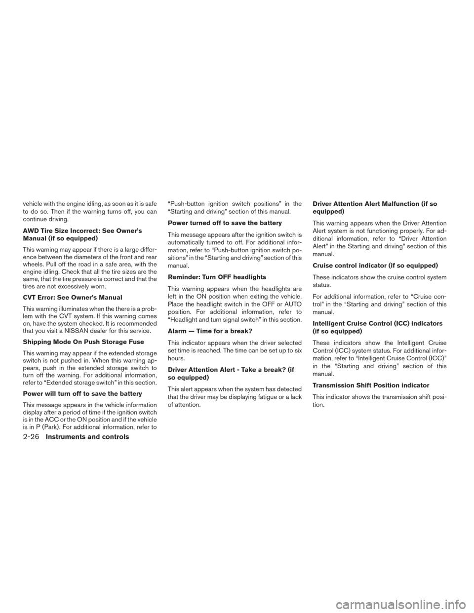
vehicle with the engine idling, as soon as it is safe
to do so. Then if the warning turns off, you can
continue driving.
AWD Tire Size Incorrect: See Owner’s
Manual (if so equipped)
This warning may appear if there is a large differ-
ence between the diameters of the front and rear
wheels. Pull off the road in a safe area, with the
engine idling. Check that all the tire sizes are the
same, that the tire pressure is correct and that the
tires are not excessively worn.
CVT Error: See Owner’s Manual
This warning illuminates when the there is a prob-
lem with the CVT system. If this warning comes
on, have the system checked. It is recommended
that you visit a NISSAN dealer for this service.
Shipping Mode On Push Storage Fuse
This warning may appear if the extended storage
switch is not pushed in. When this warning ap-
pears, push in the extended storage switch to
turn off the warning. For additional information,
refer to “Extended storage switch” in this section.
Power will turn off to save the battery
This message appears in the vehicle information
display after a period of time if the ignition switch
is in the ACC or the ON position and if the vehicle
is in P (Park) . For additional information, refer to“Push-button ignition switch positions” in the
“Starting and driving” section of this manual.
Power turned off to save the battery
This message appears after the ignition switch is
automatically turned to off. For additional infor-
mation, refer to “Push-button ignition switch po-
sitions” in the “Starting and driving” section of this
manual.
Reminder: Turn OFF headlights
This warning appears when the headlights are
left in the ON position when exiting the vehicle.
Place the headlight switch in the OFF or AUTO
position. For additional information, refer to
“Headlight and turn signal switch” in this section.
Alarm — Time for a break?
This indicator appears when the driver selected
set time is reached. The time can be set up to six
hours.
Driver Attention Alert - Take a break? (if
so equipped)
This alert appears when the system has detected
that the driver may be displaying fatigue or a lack
of attention.
Driver Attention Alert Malfunction (if so
equipped)
This warning appears when the Driver Attention
Alert system is not functioning properly. For ad-
ditional information, refer to “Driver Attention
Alert” in the Starting and driving” section of this
manual.
Cruise control indicator (if so equipped)
These indicators show the cruise control system
status.
For additional information, refer to “Cruise con-
trol” in the “Starting and driving” section of this
manual.
Intelligent Cruise Control (ICC) indicators
(if so equipped)
These indicators show the Intelligent Cruise
Control (ICC) system status. For additional infor-
mation, refer to “Intelligent Cruise Control (ICC)”
in the “Starting and driving” section of this
manual.
Transmission Shift Position indicator
This indicator shows the transmission shift posi-
tion.
2-26Instruments and controls
Page 147 of 466
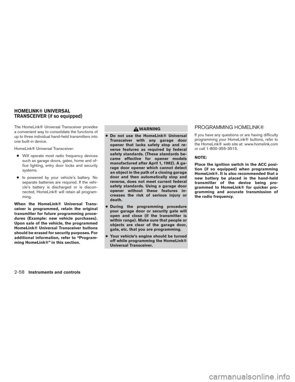
The HomeLink® Universal Transceiver provides
a convenient way to consolidate the functions of
up to three individual hand-held transmitters into
one built-in device.
HomeLink® Universal Transceiver:● Will operate most radio frequency devices
such as garage doors, gates, home and of-
fice lighting, entry door locks and security
systems.
● Is powered by your vehicle’s battery. No
separate batteries are required. If the vehi-
cle’s battery is discharged or is discon-
nected, HomeLink® will retain all program-
ming.
When the HomeLink® Universal Trans-
ceiver is programmed, retain the original
transmitter for future programming proce-
dures (Example: new vehicle purchases) .
Upon sale of the vehicle, the programmed
HomeLink® Universal Transceiver buttons
should be erased for security purposes. For
additional information, refer to “Program-
ming HomeLink®” in this section.WARNING
● Do not use the HomeLink® Universal
Transceiver with any garage door
opener that lacks safety stop and re-
verse features as required by federal
safety standards. (These standards be-
came effective for opener models
manufactured after April 1, 1982) . A ga-
rage door opener which cannot detect
an object in the path of a closing garage
door and then automatically stop and
reverse, does not meet current federal
safety standards. Using a garage door
opener without these features in-
creases the risk of serious injury or
death.
● During the programming procedure
your garage door or security gate will
open and close (if the transmitter is
within range) . Make sure that people or
objects are clear of the garage door,
gate, etc. that you are programming.
● Your vehicle’s engine should be turned
off while programming the HomeLink®
Universal Transceiver.
PROGRAMMING HOMELINK®
If you have any questions or are having difficulty
programming your HomeLink® buttons, refer to
the HomeLink® web site at: www.homelink.com
or call 1-800-355-3515.
NOTE:
Place the ignition switch in the ACC posi-
tion (if so equipped) when programming
HomeLink®. It is also recommended that a
new battery be placed in the hand-held
transmitter of the device being pro-
grammed to HomeLink® for quicker pro-
gramming and accurate transmission of
the radio frequency.
HOMELINK® UNIVERSAL
TRANSCEIVER (if so equipped)
2-58Instruments and controls
Page 150 of 466
●position the hand-held transmitter with its
battery area facing away from the
HomeLink® surface.
● press and hold both the HomeLink® and
hand-held transmitter buttons without inter-
ruption.
● position the hand-held transmitter1-3in
(26 - 76 mm) away from the HomeLink®
surface. Hold the transmitter in that position
for up to 15 seconds. If HomeLink® is not
programmed within that time, try holding the
transmitter in another position – keeping the
indicator light in view at all times.
If you have any questions or are having difficulty
programming your HomeLink® buttons, refer to
the HomeLink® web site at: www.homelink.com
or call 1-800-355-3515.
CLEARING THE PROGRAMMED
INFORMATION
The following procedure clears the programmed
information from both buttons. Individual buttons
cannot be cleared. However, individual buttons
can be reprogrammed. For additional informa-
tion, refer to “Reprogramming a single
HomeLink® button” in this section. To clear all programming:
1. Press and hold the two outer HomeLink® buttons until the indicator light begins to
flash in approximately 10 seconds. Do not
hold for longer than 20 seconds.
2. Release both buttons.
HomeLink® is now in the programming mode
and can be programmed at any time beginning
with “Programming HomeLink®” - Step 1.
REPROGRAMMING A SINGLE
HOMELINK® BUTTON
To reprogram a HomeLink® Universal Trans-
ceiver button, complete the following: 1. Press and hold the desired HomeLink® but- ton. DO NOT release the button.
2. The indicator light will begin to flash after 20 seconds. Without releasing the
HomeLink® button, proceed with “Pro-
gramming HomeLink®” - Step 1.
For questions or comments, contact HomeLink®
at: www.homelink.com or 1–800–355–3515
(except Mexico) .
The HomeLink® Universal Transceiver button
has now been reprogrammed. The new device
can be activated by pushing the HomeLink® button that was just programmed. This procedure
will not affect any other programmed HomeLink®
buttons.
IF YOUR VEHICLE IS STOLEN
If your vehicle is stolen, you should change the
codes of any non-rolling code device that has
been programmed into HomeLink®. Consult the
Owner’s Manual of each device or call the manu-
facturer or dealer of those devices for additional
information.
When your vehicle is recovered, you will
need to reprogram the HomeLink® Univer-
sal Transceiver with your new transmitter
information.
FCC Notice:
For USA:
This device complies with Part 15 of the
FCC Rules. Operation is subject to the fol-
lowing two conditions: (1) This device may
not cause harmful interference, and (2) this
device must accept any interference re-
ceived, including interference that may
cause undesired operation.
Instruments and controls2-61
Page 169 of 466
Answer back horn feature
If desired, the answer back horn feature can be
deactivated using the Intelligent Key. When it is
deactivated and the LOCK
button is
pushed, the hazard indicator lights flash twice.
When the UNLOCK
button is pushed, nei-
ther the hazard indicator lights nor the horn op-
erates. NOTE:
If you change the answer back horn and
hazard indicator lights flash feature with
the Intelligent Key, the vehicle information
display screen will show the current mode
after the ignition switch has been cycled
from the OFF to the ON position. The ve-
hicle information display screen can also
be used to change the answer back horn
mode.
To deactivate:
Press and hold the
andbuttonsfor at least 2 seconds.
The hazard indicator lights will flash three times to
confirm that the answer back horn feature has
been deactivated.
To activate: Press and hold the
andbuttonsfor at least 2 seconds once
more.
The hazard indicator lights will flash once and the
horn will sound once to confirm that the horn
beep feature has been reactivated.
Deactivating the horn beep feature does not si-
lence the horn if the alarm is triggered.
WARNING SIGNALS
To help prevent the vehicle from moving unex-
pectedly by erroneous operation of the Intelligent
Key or to help prevent the vehicle from being
stolen, a chime or buzzer sounds from inside and
outside the vehicle and a warning is displayed in
the instrument panel.
When a chime or beep sounds or a warning is
displayed, be sure to check the vehicle and the
Intelligent Key.
For additional information, refer to the “Trouble-
shooting guide” in this section and “Vehicle infor-
mation display” in the “Instruments and controls”
section of this manual.
TROUBLESHOOTING GUIDE
Verify the location of all Intelligent Keys that are
programmed for the vehicle. If another Intelligent
Key is in range or inside the vehicle, the vehicle
system may respond differently than expected.
LPD2259
3-16Pre-driving checks and adjustments
Page 171 of 466
Thebutton will be on the NISSAN Intelli-
gent Key® if the vehicle has remote engine start.
This feature allows the engine to start from out-
side the vehicle.
The following features may be affected when the
remote start feature is used:
● The vehicle’s automatic climate control sys-
tem will set the cabin temperature appropri-
ately before the customer unlocks and en-
ters the vehicle. For additional information,
refer to “Remote engine start logic” in the
“Display screen, heater, air conditioner, au-
dio, and phone systems” section of this
manual. ●
Vehicles without automatic climate control
will default to the last used heating or cool-
ing mode.
Laws in some local communities may restrict the
use of remote starters. For example, some laws
require a person using remote start to have the
vehicle in view. Check local regulations for any
requirements.
Other conditions may affect the function of the
Remote Engine Start feature. For additional infor-
mation, refer to “Conditions the remote start will
not work” in this section. Other conditions can affect the performance of
the Intelligent Key transmitter. For additional in-
formation, refer to “NISSAN Intelligent Key®” in
this section.
REMOTE ENGINE START
OPERATING RANGE
The remote engine start function can only be
used when the Intelligent Key is within the speci-
fied operating range from the vehicle.
When the Intelligent Key battery is discharged or
other strong radio wave sources are present near
the operating location, the Intelligent Key operat-
ing range becomes narrower, and the Intelligent
Key may not function properly.
The remote engine start operating range is ap-
proximately 197 ft (60 m) from the vehicle.
REMOTE STARTING THE VEHICLE
To use the remote start feature to start the engine
perform the following:
1. Aim the Intelligent Key at the vehicle.
2. Press the
LOCK button to lock all
doors.
Type A (if so equipped)
LPD2293
Type B (if so equipped)
LPD2060
REMOTE ENGINE START (if so
equipped)
3-18Pre-driving checks and adjustments
Page 177 of 466
Auto Reverse:
If an obstacle is detected during power open or
power close, a warning chime will sound and the
liftgate will reverse direction and return to the full
open or full close position. If a second obstacle is
detected, the liftgate motion will stop and the
liftgate will enter manual mode.
A pinch strip is mounted on each side of the
liftgate. If an obstacle is detected by a pinch strip
during power close, the liftgate will reverse direc-
tion and return to the full open position.
NOTE:
If the pinch strip is damaged or removed,
the power close function will not operate.
WARNING
There are some small distances immedi-
ately before the closed position which
cannot be detected. Make sure that all
passengers have their hands, etc., inside
the vehicle before closing the liftgate.Manual Mode:
If power operation is not available, the liftgate
may be operated manually. Power operation may
not be available if the power liftgate main switch
is in the ON position, if multiple obstacles have
been detected in a single power cycle, or if
battery voltage is low.
If the liftgate opener switch is pushed during
power open or close, the power operation will be
canceled and the liftgate can be operated manu-
ally.
To open the liftgate manually, press the liftgate
opener switch and lift the liftgate. To close, lower and push the liftgate down se-
curely.
Auto Power Liftgate System Battery Power
Saving Mode:
The vehicle goes into power saving mode when
the liftgate is open for a long time (approximately
12 hours) . This is to prevent deterioration of the
battery. The power saving mode automatically
cuts the power supply of the power liftgate door.
When the power to the liftgate is cut off, the
manual mode must be performed. After the
manual mode is performed, the power liftgate
function is restored.
NOTE:
When a battery voltage is lower than ap-
proximately 11V, the power liftgate may not
operate after automatic return.
LPD2297
3-24Pre-driving checks and adjustments