Page 108 of 318

3 Pre-driving checks and adjustments
Keys .............................................3-2NISSAN Vehicle Immobilizer System keys .........3-2
Doors ............................................3-3
Locking with key ................................3-3
Locking with inside lock knob ....................3-4
Locking with power door lock switch
(if so equipped) ................................3-4
Automatic door locks (if so equipped). . . ..........3-5
Child safety rear door lock .......................3-5
Remote keyless entry system (if so equipped) .........3-5
How to use remote keyless entry system ..........3-6
Hood ............................................3-8
Rear hatch (Hatchback) ............................3-9 Opening the rear hatch
..........................3-9
Fuel-filler door ................................... 3-10
Opener operation .............................. 3-10
Fuel-filler cap ................................. 3-10
Steering wheel ................................... 3-12
Tilt operation .................................. 3-12
Sun visors ....................................... 3-12
Vanity mirrors (if so equipped) ...................3-13
Card holder (driver’s side only)
(if so equipped) ............................... 3-13
Mirrors .......................................... 3-14
Rearview mirror ............................... 3-14
Outside mirrors ............................... 3-14
Page 120 of 318
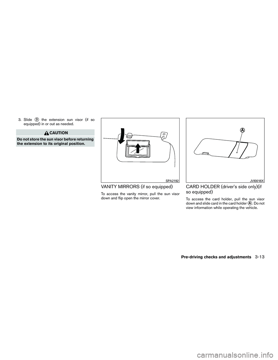
3. Slide�3the extension sun visor (if so
equipped) in or out as needed.
CAUTION
Do not store the sun visor before returning
the extension to its original position.
VANITY MIRRORS (if so equipped)
To access the vanity mirror, pull the sun visor
down and flip open the mirror cover.
CARD HOLDER (driver’s side only)(if
so equipped)
To access the card holder, pull the sun visor
down and slide card in the card holder
�A. Do not
view information while operating the vehicle.
SPA2192JVI0018X
Pre-driving checks and adjustments3-13
Page 121 of 318
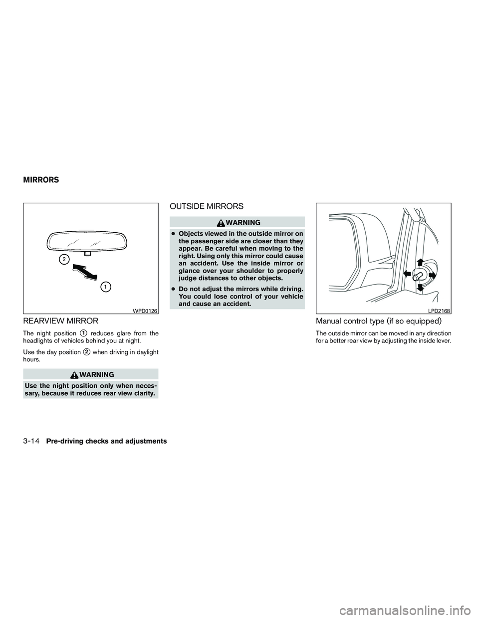
REARVIEW MIRROR
The night position�1reduces glare from the
headlights of vehicles behind you at night.
Use the day position
�2when driving in daylight
hours.
WARNING
Use the night position only when neces-
sary, because it reduces rear view clarity.
OUTSIDE MIRRORS
WARNING
● Objects viewed in the outside mirror on
the passenger side are closer than they
appear. Be careful when moving to the
right. Using only this mirror could cause
an accident. Use the inside mirror or
glance over your shoulder to properly
judge distances to other objects.
● Do not adjust the mirrors while driving.
You could lose control of your vehicle
and cause an accident.
Manual control type (if so equipped)
The outside mirror can be moved in any direction
for a better rear view by adjusting the inside lever.
WPD0126LPD2168
MIRRORS
3-14Pre-driving checks and adjustments
Page 122 of 318

The outside mirror remote control will operate
only when the ignition switch is in the ACC or ON
position.
Move the small switch
�1to select the right or left
mi")
Electric control type (if so equipped)
The outside mirror remote control will operate
only when the ignition switch is in the ACC or ON
position.
Move the small switch
�1to select the right or left
mirror. Adjust each mirror to the desired position
using the large switch
�2.
WARNING
● Objects viewed in the outside mirror on
the passenger side are closer than they
appear. Be careful when moving to the
right. Using only this mirror could cause
an accident. Use the inside mirror or
glance over your shoulder to properly
judge distances to other objects.
● Do not adjust the mirrors while driving.
You could lose control of your vehicle
and cause an accident.
Manual folding outside mirrors
Pull the outside mirror toward the door to fold it.
Heated mirrors (if so equipped)
The outside mirrors can be heated to defrost,
defog, or de-ice for improved visibility. For addi-
tional information, refer to “Rear window and
outside mirror (if so equipped) defroster switch”
in the “Instruments and controls” section of this
manual.
LPD0237WPD0056
Pre-driving checks and adjustments3-15
Page 125 of 318
WARNING
●Failure to follow the warnings and in-
structions for proper use of the Rear-
View Monitor system could result in se-
rious injury or death. ●
RearView Monitor is a convenience fea-
ture and is not a substitute for proper
backing. Always turn and look out the
windows and check mirrors to be sure
that it is safe to move before operating
the vehicle. Always back up slowly. ●
The system is designed as an aid to the
driver in showing large stationary ob-
jects directly behind the vehicle, to help
avoid damaging the vehicle.
LHA3823
REARVIEW MONITOR (if so
equipped)
4-2Heater, air conditioner, audio and phone systems
Page 129 of 318

ADJUSTING THE SCREEN
The procedure for adjusting the display settings
of the screen differs depending on the type of
screen present on the vehicle.1. Firmly apply the brake and place the shift lever in R (reverse) .
2. Press the ENTER/SETTING button.
3. The screen will display the Brightness set- tings.
4. Turn the TUNE/FOLDER knob to adjust the setting up or down. 5. Press the ENTER/SETTING button again to
display the Contrast settings.
6. Turn the TUNE/FOLDER knob to adjust the setting up or down.
7. Press the ENTER/SETTING button to com- plete the adjustment.
NOTE:
Do not adjust any of the display settings of
the RearView Monitor while the vehicle is
moving. Make sure the parking brake is
firmly applied.
REARVIEW MONITOR SYSTEM
LIMITATIONS
WARNING
Listed below are the system limitations for
RearView Monitor. Failure to operate the
vehicle in accordance with these system
limitations could result in serious injury or
death.
● The system cannot completely elimi-
nate blind spots and may not show ev-
ery object. ●
Underneath the bumper and the corner
areas of the bumper cannot be viewed
on the RearView Monitor because of its
monitoring range limitation. The system
will not show small objects below the
bumper, and may not show objects
close to the bumper or on the ground.
● Objects viewed in the RearView Moni-
tor differ from actual distance because
a wide-angle lens is used.
● Objects in the RearView Monitor will
appear visually opposite compared to
when viewed in the rearview and out-
side mirrors.
● Use the displayed lines as a reference.
The lines are highly affected by the
number of occupants, fuel level, vehicle
position, road conditions and road
grade.
● Make sure that the rear hatch is se-
curely closed when backing up.
● Do not put anything on the rearview
camera. The rearview camera is in-
stalled above the license plate.
LHA3639
4-6Heater, air conditioner, audio and phone systems
Page 133 of 318

— Air flows from defroster outlets andthe front and rear floor outlets.
— Air flows mainly from defrosteroutlets.
Temperature control dial
The temperature control dial allows you to adjust
the temperature of the outlet air. To lower the
temperature, turn the dial to the left. To increase
the temperature, turn the dial to the right.
Fresh air
Move the air intake lever to theposition.
The air flow is drawn from outside the vehicle.
Air recirculation
Move the air intake lever to theposition to
recirculate air inside the vehicle.
Use the
selection:
● when driving on a dusty road.
● to prevent traffic fumes from entering pas-
senger compartment.
● for maximum cooling when using the air con-
ditioner.
Air conditioner button (if so
equipped)
Start the engine, turn thefan control dial to
the desired position and press the
button
to turn on the air conditioner. The indicator light
comes on when the air conditioner is operating.
To turn off the air conditioner, press the
button again.
Rear window and outside mirror (if so
equipped) defroster switch
For additional information, refer to “Rear window
and outside mirror (if so equipped) defroster
switch” in the “Instruments and controls” section
of this manual.
HEATER OPERATION
Heating
This mode is used to direct heated air to the foot
outlets. Some air also flows from the defrost
outlets.
1. Move the air intake lever to the
posi-
tion for normal heating.
2. Turn the air flow control dial to the
position.
3. Turn the
fan control dial to the desired
position. 4. Turn the temperature control dial to the de-
sired position between the middle and the
hot position.
Ventilation
This mode directs outside air to the side and
center vents.
1. Move the air intake lever to the
posi-
tion.
2. Turn the air flow control dial to the
position.
3. Turn the
fan control dial to the desired
position.
4. Turn the temperature control dial to the de- sired position.
Defrosting or defogging
This mode directs the air to the defrost outlets to
defrost/defog the windows.
1. Move the air intake lever to the
posi-
tion.
2. Turn the air flow control dial to the
position.
3. Turn the
fan control dial to the desired
position.
4-10Heater, air conditioner, audio and phone systems
Page 140 of 318
 defroster switch
2.
Fan speed control dial
3. A/C (air conditioner) button
4. Temperature control dial
5. Air intake lever (Air recirculation")
CONTROLS
1.Rear window and outside mirror (if so
equipped) defroster switch
2.
Fan speed control dial
3. A/C (air conditioner) button
4. Temperature control dial
5. Air intake lever (Air recirculation and Fresh air)
6. Air flow control dial
Fan control dial
Thefan control dial turns the fan on and off
and controls fan speed.
Air flow control dial
The air flow control dial allows you to select the
air flow outlets.
— Air flows from center and side vents.
— Air flows from center and side vents
and foot outlets.
— Air flows mainly from foot outlets.
— Air flows from defroster outlets andfoot outlets.
— Air flows mainly from defrosteroutlets.
Temperature control dial
The temperature control dial allows you to adjust
the temperature of the outlet air. To lower the
temperature, turn the dial to the left. To increase
the temperature, turn the dial to the right.
Fresh air
Move the air intake lever to theposition.
The air flow is drawn from outside the vehicle.
Air recirculation
Move the air intake lever to theposition to
recirculate air inside the vehicle.
Use the
selection:
● when driving on a dusty road.
● to prevent traffic fumes from entering pas-
senger compartment.
● for maximum cooling when using the air con-
ditioner.
Air conditioner button
Start the engine, turn the fan control dial to the
desired position and press the
button to
turn on the air conditioner. The indicator light
LHA3531
Heater, air conditioner, audio and phone systems4-17