2017 NISSAN MAXIMA power steering
[x] Cancel search: power steeringPage 14 of 406
17. Push-button ignition switch (P. 5-10)
18. Bluetooth® Hands-Free Phone System(P. 4-30)
Cruise control switches
(if so equipped) (P. 5-40)
Intelligent Cruise Control (ICC)
switches (if so equipped) (P. 5-42)
19. Tilt and telescopic steering (P. 3-26)
20. Audio control switches* Vehicle information display control
switches (P. 2-16)
21. Hood release (P. 3-21)
22. Fuse box (P. 8-18)
23. Heated steering wheel switch
(if so equipped) (P. 2-48)
Vehicle Dynamic Control (VDC) OFF
switch (P. 2-49)
Trunk release switch (P. 3-22)
Rear power sunshade switch
(if so equipped) (P. 2-61)
24. Instrument brightness control (P. 2-42) Twin trip odometer reset switch (P. 2-4)
*: Refer to the separate Navigation System Own-
er’s Manual.
Refer to the page number indicated in pa-
rentheses for operating details.
Illustrated table of contents0-7
Page 15 of 406
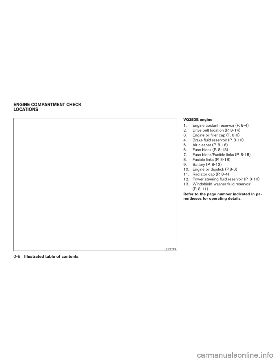
VQ35DE engine
1. Engine coolant reservoir (P. 8-4)
2. Drive belt location (P. 8-14)
3. Engine oil filler cap (P. 8-6)
4. Brake fluid reservoir (P. 8-10)
5. Air cleaner (P. 8-16)
6. Fuse block (P. 8-18)
7. Fuse block/Fusible links (P. 8-18)
8. Fusible links (P. 8-18)
9. Battery (P. 8-12)
10. Engine oil dipstick (P.8-6)
11. Radiator cap (P. 8-4)
12. Power steering fluid reservoir (P. 8-10)
13. Windshield-washer fluid reservoir(P. 8-11)
Refer to the page number indicated in pa-
rentheses for operating details.
LDI2749
ENGINE COMPARTMENT CHECK
LOCATIONS
0-8Illustrated table of contents
Page 16 of 406
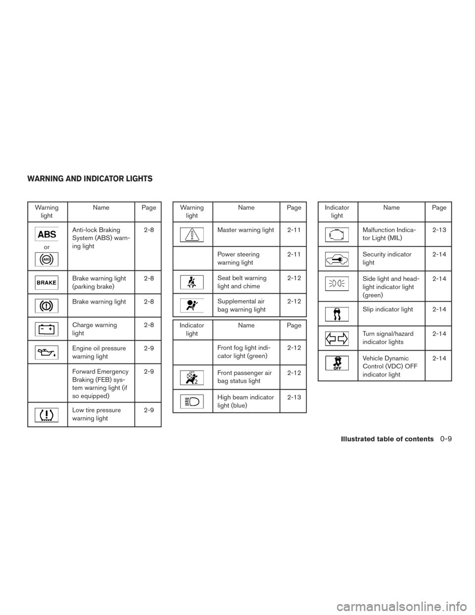
Warninglight Name Page
or
Anti-lock Braking
System (ABS) warn-
ing light 2-8
Brake warning light
(parking brake)
2-8
Brake warning light 2-8
Charge warning
light2-8
Engine oil pressure
warning light2-9
Forward Emergency
Braking (FEB) sys-
tem warning light (if
so equipped)2-9
Low tire pressure
warning light
2-9
Warning
light Name Page
Master warning light 2-11
Power steering
warning light 2-11
Seat belt warning
light and chime2-12
Supplemental air
bag warning light2-12
Indicator
light Name Page
Front fog light indi-
cator light (green) 2-12
Front passenger air
bag status light2-12
High beam indicator
light (blue)2-13
Indicator
light Name Page
Malfunction Indica-
tor Light (MIL) 2-13
Security indicator
light2-14
Side light and head-
light indicator light
(green)2-14
Slip indicator light 2-14
Turn signal/hazard
indicator lights
2-14
Vehicle Dynamic
Control (VDC) OFF
indicator light2-14
WARNING AND INDICATOR LIGHTS
Illustrated table of contents0-9
Page 82 of 406
17. Push-button ignition switch (P. 5-10)
18. Bluetooth® Hands-Free Phone System(P. 4-30)
Cruise control switches
(if so equipped) (P. 5-40)
Intelligent Cruise Control (ICC)
switches (if so equipped) (P. 5-42)
19. Tilt and telescopic steering (P. 3-26)
20. Audio control switches* Vehicle information display control
switches (P. 2-16)
21. Hood release (P. 3-21)
22. Fuse box (P. 8-18)
23. Heated steering wheel switch
(if so equipped) (P. 2-48)
Vehicle Dynamic Control (VDC) OFF
switch (P. 2-49)
Trunk release switch (P. 3-22)
Rear power sunshade switch (if so
equipped) (P. 2-61)
24. Instrument brightness control (P. 2-42) Twin trip odometer reset switch (P. 2-4)
*: Refer to the separate Navigation System Own-
er’s Manual.
Refer to the page number indicated in pa-
rentheses for operating details.1. Tachometer
2. Warning and indicator lights
3. Vehicle information displayOdometer
Twin trip odometer
4. Speedometer 5. Fuel gauge
6. Engine coolant temperature gauge
LIC3191
METERS AND GAUGES
Instruments and controls2-3
Page 86 of 406
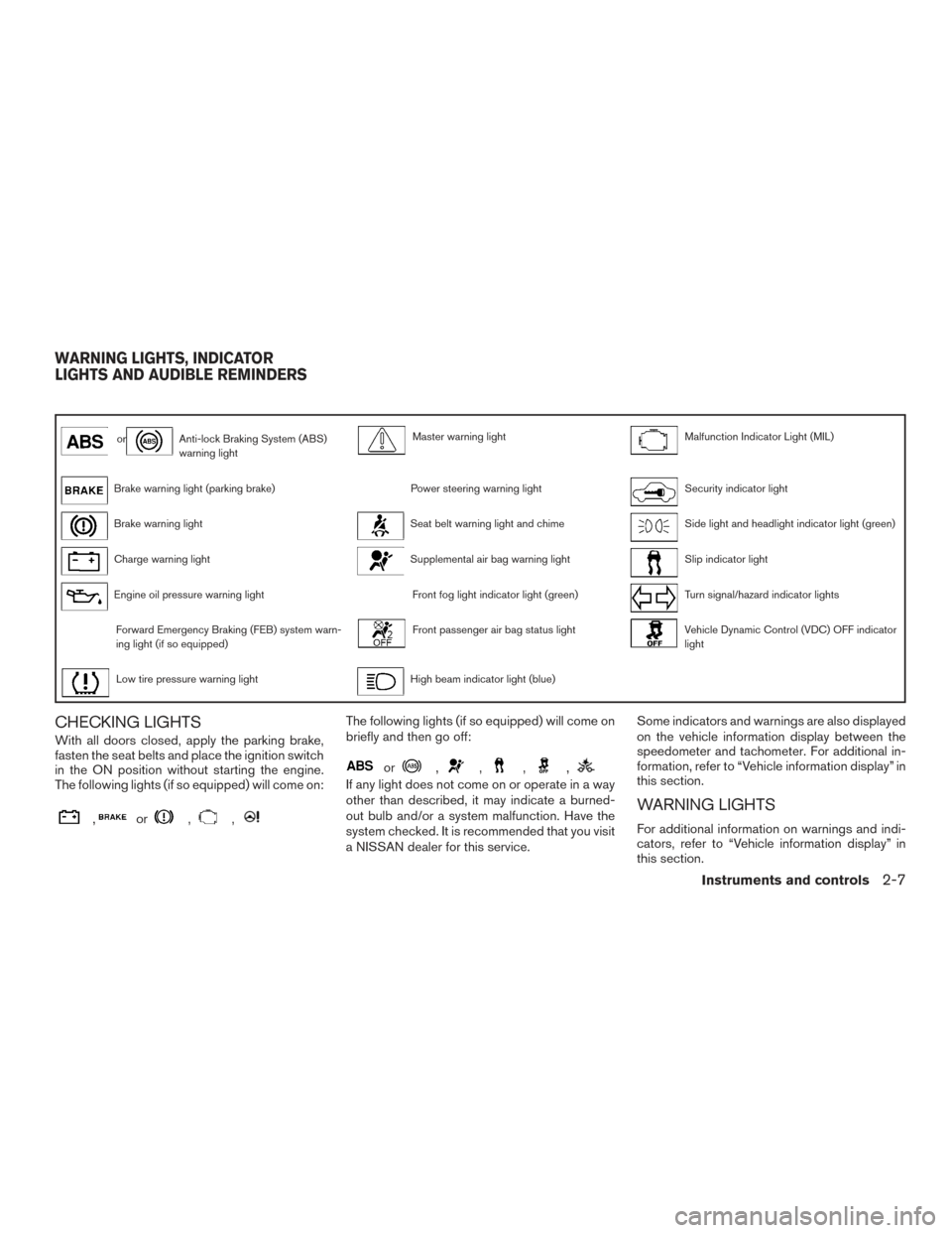
orAnti-lock Braking System (ABS)
warning lightMaster warning lightMalfunction Indicator Light (MIL)
Brake warning light (parking brake)Power steering warning lightSecurity indicator light
Brake warning lightSeat belt warning light and chimeSide light and headlight indicator light (green)
Charge warning lightSupplemental air bag warning lightSlip indicator light
Engine oil pressure warning lightFront fog light indicator light (green)Turn signal/hazard indicator lights
Forward Emergency Braking (FEB) system warn-
ing light (if so equipped)Front passenger air bag status lightVehicle Dynamic Control (VDC) OFF indicator
light
Low tire pressure warning lightHigh beam indicator light (blue)
CHECKING LIGHTS
With all doors closed, apply the parking brake,
fasten the seat belts and place the ignition switch
in the ON position without starting the engine.
The following lights (if so equipped) will come on:
,or,,
The following lights (if so equipped) will come on
briefly and then go off:
or,,,,
If any light does not come on or operate in a way
other than described, it may indicate a burned-
out bulb and/or a system malfunction. Have the
system checked. It is recommended that you visit
a NISSAN dealer for this service.Some indicators and warnings are also displayed
on the vehicle information display between the
speedometer and tachometer. For additional in-
formation, refer to “Vehicle information display” in
this section.
WARNING LIGHTS
For additional information on warnings and indi-
cators, refer to “Vehicle information display” in
this section.
WARNING LIGHTS, INDICATOR
LIGHTS AND AUDIBLE REMINDERS
Instruments and controls2-7
Page 90 of 406
CAUTION
●The TPMS is not a substitute for the
regular tire pressure check. Be sure to
check the tire pressure regularly.
● If the vehicle is being driven at speeds
of less than 16 mph (25 km/h), the
TPMS may not operate correctly.
● Be sure to install the specified size of
tires to the four wheels correctly.
Master warning light
The master warning light illuminates whenever
there is an active warning that can be reviewed in
the “warnings review” content page in the meter,
or if there is a red-level warning being displayed
(which cannot be dismissed) . The master warn-
ing light will illuminate red if a red-level warning is
being displayed, or yellow otherwise.
● Push Engine Start Lock Warning
● Key Fob Removed from Vehicle Warning
● Incorrect Key (RED)
● Door/Trunk Open (vehicle stationary)
● Trunk Open (vehicle moving)
● Door Open (RED with vehicle moving) ●
Parking Brake ON (RED)
● Low Washer Fluid
● I-Key System Fault
● Low Tire Pressure
● CVT Warning
● Sonar Parking Sensor Error
● LED Headlight Failure (RED if no other red
warnings are active)
● Chassis Control warning
For additional information, refer to “Vehicle infor-
mation display” in this section.
Power steering warning light
WARNING
● If the engine is not running or is turned
off while driving, the power assist for
the steering will not work. Steering will
be harder to operate. ●
When the power steering warning light
illuminates with the engine running,
there will be no power assist for the
steering. You will still have control of
the vehicle, but the steering will be
harder to operate. Have the power
steering system checked. It is recom-
mended that you visit a NISSAN dealer
for this service.
When the ignition switch is placed in the ON
position, the power steering warning light illumi-
nates. After starting the engine, the power steer-
ing warning light turns off. This indicates the
power steering is operational.
If the power steering warning light illuminates
while the engine is running, it may indicate the
power steering is not functioning properly and
may need servicing. Have the power steering
checked. It is recommended that you visit a
NISSAN dealer for this service.
When the power steering warning light illumi-
nates with the engine running, there will be no
power assist for the steering, but you will still
have control of the vehicle. At this time, greater
steering effort is required to operate the steering
wheel, especially in sharp turns and at low
speeds.
Instruments and controls2-11
Page 128 of 406
NOTE:
If the surface temperature of the steering
wheel is above 68°F (20°C) when the switch
is turned on, the system will not heat the
steering wheel. This is not a malfunction.The vehicle should be driven with the VDC sys-
tem on for most driving conditions.
If the vehicle is stuck in mud or snow, the VDC
system reduces the engine output to reduce
wheel spin. The engine speed will be reduced
even if the accelerator is depressed to the floor. If
maximum engine power is needed to free a stuck
vehicle, turn the VDC system off.
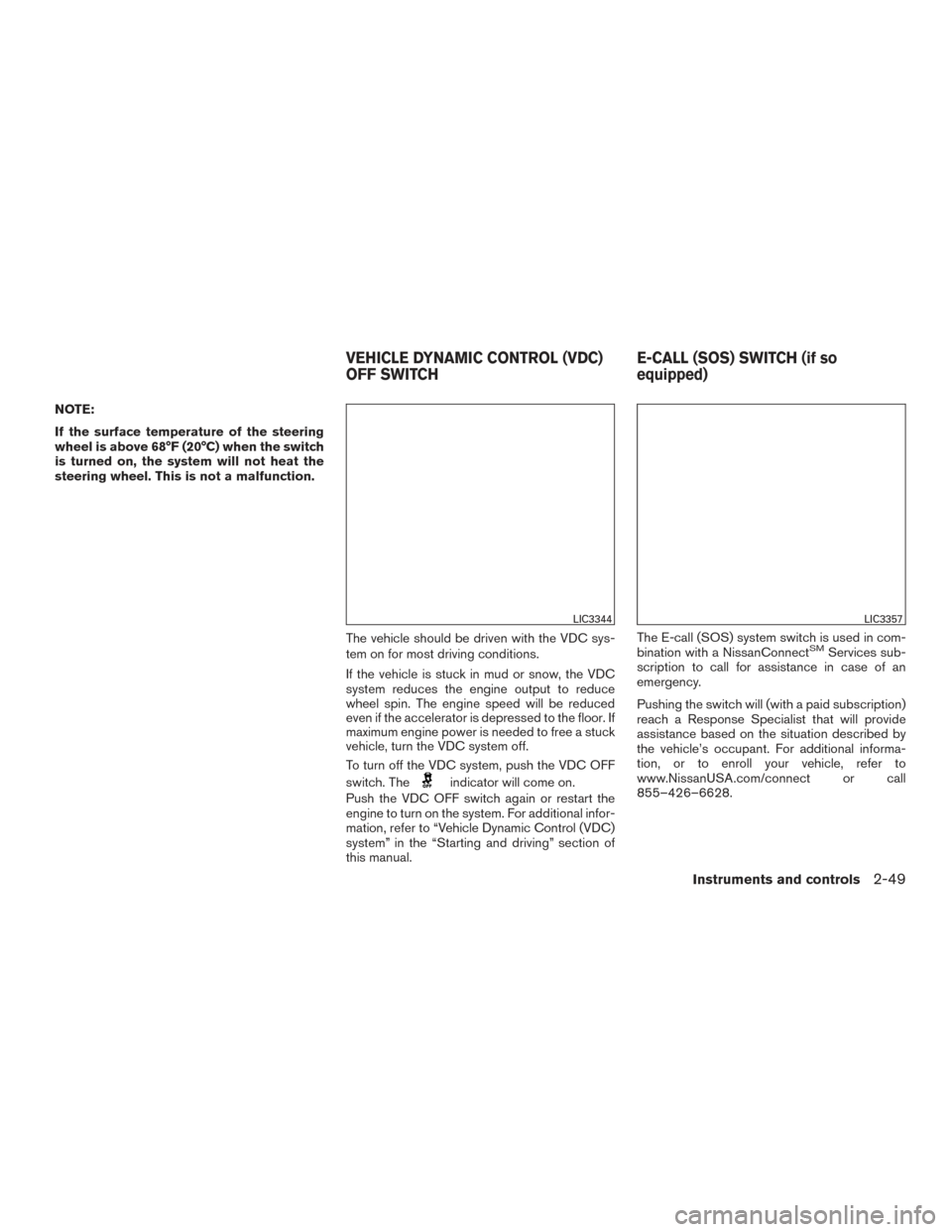
To turn off the VDC system, push the VDC OFF
switch. The
indicator will come on.
Push the VDC OFF switch again or restart the
engine to turn on the system. For additional infor-
mation, refer to “Vehicle Dynamic Control (VDC)
system” in the “Starting and driving” section of
this manual. The E-call (SOS) system switch is used in com-
bination with a NissanConnect
SMServices sub-
scription to call for assistance in case of an
emergency.
Pushing the switch will (with a paid subscription)
reach a Response Specialist that will provide
assistance based on the situation described by
the vehicle’s occupant. For additional informa-
tion, or to enroll your vehicle, refer to
www.NissanUSA.com/connect or call
855–426–6628.
LIC3344LIC3357
VEHICLE DYNAMIC CONTROL (VDC)
OFF SWITCH E-CALL (SOS) SWITCH (if so
equipped)
Instruments and controls2-49
Page 129 of 406
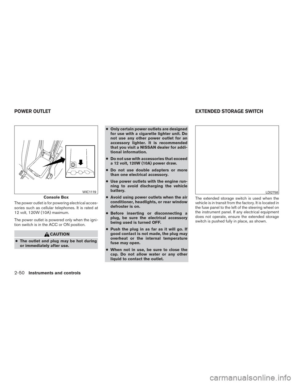
The power outlet is for powering electrical acces-
sories such as cellular telephones. It is rated at
12 volt, 120W (10A) maximum.
The power outlet is powered only when the igni-
tion switch is in the ACC or ON position.
CAUTION
●The outlet and plug may be hot during
or immediately after use. ●
Only certain power outlets are designed
for use with a cigarette lighter unit. Do
not use any other power outlet for an
accessory lighter. It is recommended
that you visit a NISSAN dealer for addi-
tional information.
● Do not use with accessories that exceed
a 12 volt, 120W (10A) power draw.
● Do not use double adapters or more
than one electrical accessory.
● Use power outlets with the engine run-
ning to avoid discharging the vehicle
battery.
● Avoid using power outlets when the air
conditioner, headlights, or rear window
defroster is on.
● Before inserting or disconnecting a
plug, be sure the electrical accessory
being used is turned OFF.
● Push the plug in as far as it will go. If
good contact is not made, the plug may
overheat or the internal temperature
fuse may open.
● When not in use, be sure to close the
cap. Do not allow water or any other
liquid to contact the outlet. The extended storage switch is used when the
vehicle is in transit from the factory. It is located in
the fuse panel to the left of the steering wheel on
the instrument panel. If any electrical equipment
does not operate, ensure the extended storage
switch is pushed fully in place, as shown.
Console Box
WIC1119LDI2758
POWER OUTLET
EXTENDED STORAGE SWITCH
2-50Instruments and controls