Page 7 of 39
1-1.2 Interior Component Location
Interior
components referenced in this manual are as follows: Charging indicator lights
Power switch
Hood r
elease Selector lever
READY indicator (green)
Charge connector
lock switch
AAYIA0044GBRAG–7
Page 12 of 39

3. Roadside Assistance Response Steps
• NEVER assume the LEAF is shut OFF simply because it is quiet.
• If the vehicle is damaged and you are not sure about the condition of the electric
vehicle system, contact first responders immediately. If the vehicle is damaged, the
high-voltage system should be shut down by first responders while following the
procedures in the First Responders Guide and while wearing appropriate Personal
Protective Equipment (PPE) .
• If the READY indicator or charging indicator are ON, the high-voltage system
is
active.
• If possible, be sure to verify that the READY indicator on the instrument cluster
is
OFF and the high-voltage system is stopped.
• Some of the under hood parts get hot and may cause serious burns. Use caution when working on or around these parts.
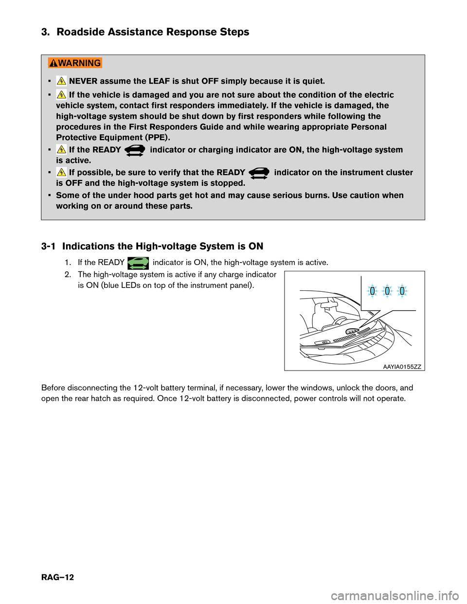
3-1 Indications the High-voltage System is ON 1. If the READY indicator is ON, the high-voltage system is active.
2.
The high-voltage system is active if any charge indicator
is ON (blue LEDs on top of the instrument panel) .
Before disconnecting the 12-volt battery terminal, if necessary, lower the windows, unlock the doors, and
open the rear hatch as required. Once 12-volt battery is disconnected, power controls will not operate. AAYIA0155ZZ
RAG–12
Page 13 of 39
3-2 Vehicle Immobilization and Stabilization
If
possible, immobilize the vehicle by turning the 12V system OFF and stabilize it with a wheel chock(s) .
Stabilize the vehicle with wooden blocks or by removing air from the tires. • Do not stabilize the vehicle with wooden blocks under the high-voltage battery.
•
To avoid electrical shock, do not put wooden blocks or wheel chock(s) under the
high-voltage components and harnesses as shown following. AAYIA0191GB
RAG–13
Page 25 of 39

Rear Tie Down Hook:
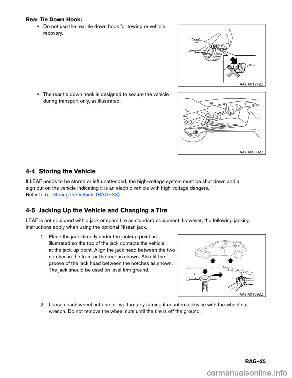
• Do not use the rear tie down hook for towing or vehicle
recovery.
• The rear tie down hook is designed to secure the vehicle during transport only, as illustrated.
4-4 Storing the Vehicle
If LEAF needs to be stored or left unattended, the high-voltage system must be shut down and a
sign put on the vehicle indicating it is an electric vehicle with high-voltage dangers.
Refer to 5. Storing the Vehicle (RAG–33)
4-5 Jacking Up the Vehicle and Changing a Tire
LEAF
is not equipped with a jack or spare tire as standard equipment. However, the following jacking
instructions apply when using the optional Nissan jack.
1. Place the jack directly under the jack-up point asillustrated so the top of the jack contacts the vehicle
at the jack-up point. Align the jack head between the two
notches in the front or the rear as shown. Also fit the
groove of the jack head between the notches as shown.
The jack should be used on level firm ground.
2. Loosen each wheel nut one or two turns by turning it counterclockwise with the wheel nut wrench. Do not remove the wheel nuts until the tire is off the ground. AAYIA0124ZZ
AAYIA0088ZZ
AAYIA0109ZZ
RAG–25
Page 30 of 39
2. Take the hose (1) and power plug (2) out of the air
compressor. Remove the cap of the bottle holder from
the air compressor.
3. Remove the cap from the tire sealant bottle and screw the bottle clockwise onto the bottle holder. Leave the
bottle seal intact. Screwing the bottle onto the bottle
holder will pierce the seal of the bottle.
4. Remove the cap from the tire valve on the flat tire.
5. Remove the protective cap (A) of the hose and screw the hose securely onto the tire valve. Make sure that the
pressure release valve (B) is securely tightened. Make
sure that the air compressor switch is in the OFF (O)
position and then insert the power plug into the power
outlet in the vehicle.
6. Push the vehicle power switch to the ACC position. 2
1
AAYIA0132ZZ AAYIA0133ZZ
B
A
AAYIA0134ZZ
RAG–30
Page 37 of 39
4. Insert a suitable tool (1) under the RH rear corner of the
access trim cover located on the floor behind the center
console. Pry up (2) and remove.
NOTE: : Arrow in illustration depicts vehicle front
direction.
5.
Remove the 10 mm access cover bolts (1) and remove
the cover (2) .
NOTE: : Arrow in illustration depicts vehicle front
direction.
6.
Remove the service plug using the following steps: (1) pull up and release the green lever, (2)
press the locking tab to release and rotate fully upward, (3) pull the service plug completely out
of its socket. 12
AAYIA0159ZZ
1
2
AAYIA0158ZZ
1
2
3
Pull up Rotate
Push to
release Pull up
and
remove
AAYIA0048GBRAG–37