Page 4 of 44
1. About The Nissan LEAF®
This
vehicle uses two types of batteries. One is a 12-volt battery that is the same as the battery in vehicles
powered by internal combustion engines, and the other is the high-voltage battery for the traction motor
which propels the vehicle. The high-voltage battery is encased in steel and mounted underneath the vehicle.
The vehicle must be plugged-in in order for the high-voltage battery to be recharged. Additionally, the
vehicle system can recharge the high-voltage battery by converting driving force into electricity while the
vehicle is decelerating or being driven downhill. This is called regenerative charging. This vehicle is
considered to be an environmentally friendly vehicle because it does not emit exhaust gases.
FRG–4
Page 6 of 44
1-1.2 Interior Component Location
Interior
components referenced in this manual are as follows: Charging indicator lights
Power switch
Hood r
elease Selector lever
READY indicator (green)
Charge connector
lock switch
AAYIA0044GB
FRG–6
Page 10 of 44

2-1.1 High-Voltage Battery Pack Specifications
High-voltage battery voltage
360V nominal
(240V - 398.4V usable range)
Number of high-voltage battery modules in the pack 48
High-voltage battery dimensions 60.91 x 46.77 x 10.39 in. (1547 x 1188 x 264 mm)
High-voltage battery weight US: 648 lbs (294 kg)
Canada: 653 lbs (296 kg)
2-2 High-Voltage Safety Measures Circuit insulation
The high-voltage positive (+) and negative (-) circuits are insulated from the
metal
chassis.
Reducing the risk of
electrocution The high-voltage components and harnesses have insulated cases or orange-
colored coverings which provide insulation and easy identification.
The high-voltage battery case is electrically connected to the vehicle ground.
This connection helps protect the vehicle occupants and emergency
responders from high-voltage electrical shock.
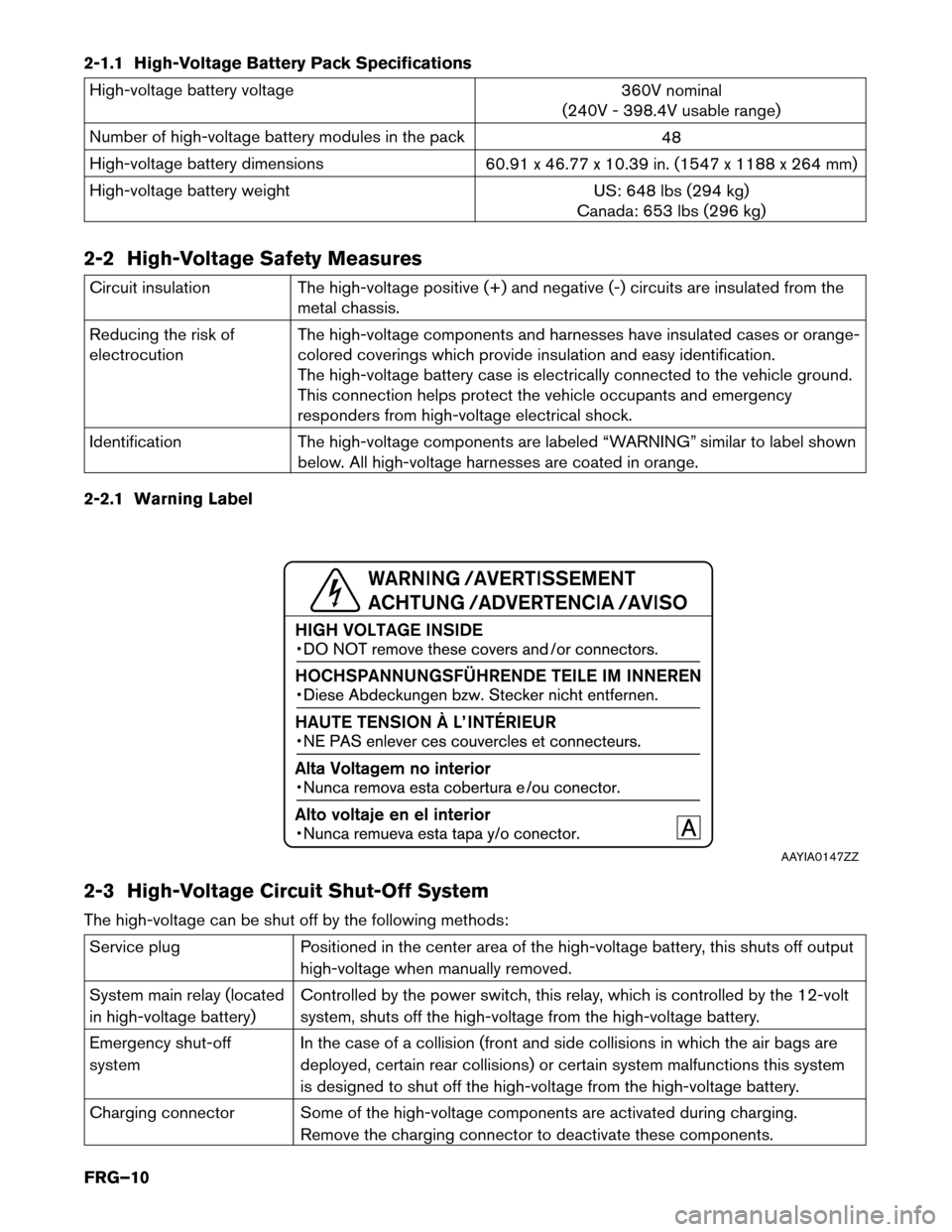
Identification The high-voltage components are labeled “WARNING” similar to label shown
below. All high-voltage harnesses are coated in orange.
2-2.1 Warning Label
2-3 High-Voltage Circuit Shut-Off System
The high-voltage can be shut off by the following methods: Service plug
Positioned in the center area of the high-voltage battery, this shuts off output
high-voltage
when manually removed.
System main relay (located
in high-voltage battery) Controlled by the power switch, this relay, which is controlled by the 12-volt
system, shuts off the high-voltage from the high-voltage battery.
Emergency shut-off
system In the case of a collision (front and side collisions in which the air bags are
deployed, certain rear collisions) or certain system malfunctions this system
is designed to shut off the high-voltage from the high-voltage battery.
Charging connector Some of the high-voltage components are activated during charging. Remove the charging connector to deactivate these components. AAYIA0147ZZ
FRG–10
Page 12 of 44

3. Emergency Response Steps
• Failure to properly shut down the high-voltage electrical system before the
Emergency Response Procedures are performed will result in serious injury or death
from electrical shock. To prevent serious injury or death, NEVER touch high-voltage
harnesses or components without always wearing appropriate Personal Protective
Equipment (PPE) .
• If it is necessary to touch any of the high-voltage harnesses or components you
must
always wear appropriate PPE to avoid electrical shock. Shut down the
high-voltage system by following the steps outlined in 3-3.1 High-voltage System
Shut-Down
Procedures (FRG–17) . Wait at least ten (10) minutes for complete
discharge
of the high-voltage capacitor after the high-voltage system has been
shut down. • NEVER assume the LEAF is shut OFF simply because it is quiet.
• If the READY indicator or charging indicator are ON, the high-voltage system
is
active.
• If possible, be sure to verify that the READY indicator on the instrument
cluster
is OFF and the high-voltage system is stopped.
• Some of the under hood parts get hot and may cause serious burns. Use caution when working on or around these parts.
FRG–12
Page 18 of 44

• If the charge connector is connected to the vehicle, remove it. Refer to
Removing the
Charge
Connector (FRG–19) .
• The vehicle contains parts that contain powerful magnets. If a person who is wearing a
pacemaker
or other medical device is close to these parts, the medical device may be
affected by the magnets. Such persons must not perform work on the vehicle.
• Be sure to verify that the READY indicator is off and the high-voltage system is
stopped.
•
After the high-voltage system is shut down, please wait at least ten (10) minutes for
complete discharge of the high-voltage capacitor. While waiting, do not operate any
vehicle functions.
NOTE:
The high-voltage full discharge takes ten (10) minutes, but after five (5) minutes the
voltage has dropped below 60V.
• After shutting down the high-voltage system and removing the 12-volt battery negative (-) terminal, wait at least three (3) minutes to discharge the air bag capacitor. Even though
the 12-volt battery negative (-) is disconnected, the Supplemental Restraint System (SRS)
air bag maintains voltage at least three (3) minutes. During this time, there is a possibility
of sudden SRS air bag inflation due to harness short circuit or damage and it may cause
serious injuries.
• Always shut down the high-voltage system before disconnecting the 12-volt battery. Not doing so may result in serious injury or death from electrical shock.
• The 12V system will remain active even after the 12-volt battery negative (-) terminal is removed while the high-voltage system is active. The high-voltage system is active
during any of the following conditions:
– charging indicator is turned ON
– READY indicator is turned ON
Refer to 1-1.2 Interior Component Location (FRG–6) for location of these indicators.
This
is because DC/DC converter will not shut down and power will be supplied to
the 12V system and high-voltage system continuously.
FRG–18