Page 19 of 48
c. The charge connector can be unlocked by
pushing the charge connector unlock button on
the Nissan Intelligent Key® for more than
1 second. The charge connector will temporarily
unlock for 30 seconds.
d. Press the charge connector release button and pull the charge connector to remove it.
3. If the Trickle or Normal Charge Connector Cannot Unlock
a. Place power switch in OFF position.
b. Open the hood.
c. Using a flat head screwdriver (or suitable tool) , insert into the screw located through the access
hole near the front of the hood lock.
d. Rotate screw clockwise to release the charge connector lock.
e. Press the charge connector release button and pull the charge connector to remove it. HOLD
NISSAN
AAYIA0153ZZ
AAYIA0091ZZ
AAYIA0145ZZ
AAYIA0353ZZ
DG–19
Page 21 of 48

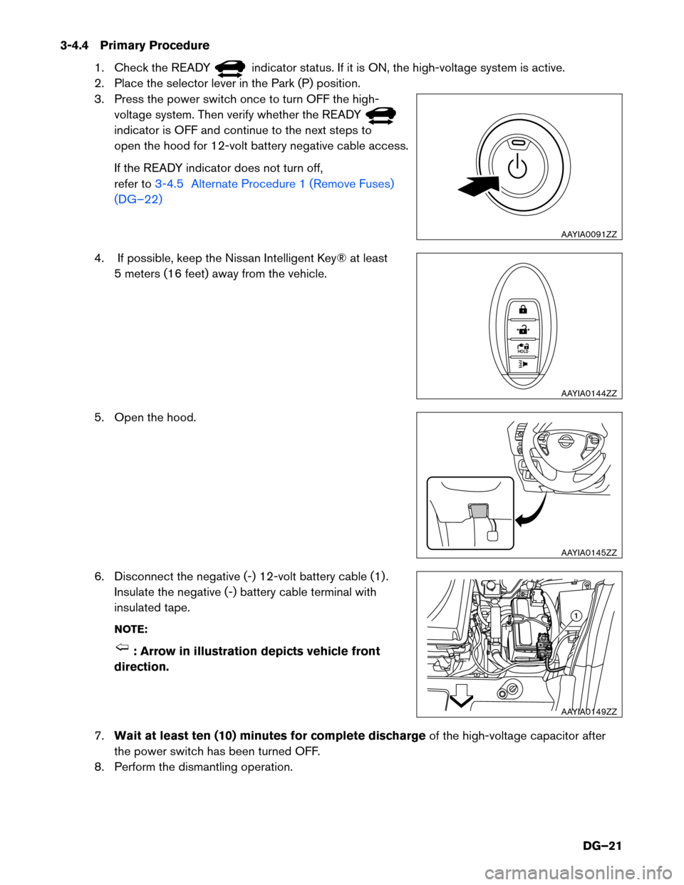
3-4.4 Primary Procedure
1. Check the READY indicator status. If it is ON, the high-voltage system is active.
2.
Place the selector lever in the Park (P) position.
3. Press the power switch once to turn OFF the high- voltage system. Then verify whether the READY indicator is OFF and continue to the next steps to
open
the hood for 12-volt battery negative cable access.
If the READY indicator does not turn off,
refer to 3-4.5 Alternate Procedure 1 (Remove Fuses)
(DG–22)
4. If possible, keep the Nissan Intelligent Key® at least 5
meters (16 feet) away from the vehicle.
5. Open the hood.
6. Disconnect the negative (-) 12-volt battery cable (1) . Insulate the negative (-) battery cable terminal with
insulated tape.
NOTE: : Arrow in illustration depicts vehicle front
direction.
7. Wait
at least ten (10) minutes for complete discharge of the high-voltage capacitor after
the power switch has been turned OFF.
8. Perform the dismantling operation. AAYIA0091ZZ
HOLD
AAYIA0144ZZ
AAYIA0145ZZ
1
AAYIA0149ZZ
DG–21
Page 22 of 48
3-4.5 Alternate Procedure 1 (Remove Fuses)
1. Open the hood.
2. Press and expand the pawls (A) on the sides of the fuse box and remove the fuse box (1) from its housing.
NOTE: : Arrow in illustration depicts vehicle front direction.
NO
TE:
There is no separate fuse box cover. The bottom of the fuse box is also its cover. AAYIA0145ZZ
1A
AAYIA0150ZZ
DG–22
Page 26 of 48
3. Remove the service plug using the following steps: (1) pull up and release the green lever, (2)
press the locking tab to release and rotate fully upward, (3) pull the service plug completely out of
its socket.
4. Wait at least (10) minutes for complete discharge of the high-voltage capacitor after the
service plug has been removed.
5. Open the hood.
6. Disconnect the negative (-) 12-volt battery cable (1) . Insulate the negative (-) battery cable terminal with
insulated tape.
NOTE: : Arrow in illustration depicts vehicle front
direction.
7.
Perform the dismantling operation. 1
2
3
Pull up Rotate
Push to
release Pull up
and
remove
AAYIA0048GB AAYIA0145ZZ
1
AAYIA0149ZZ
DG–26