2017 NISSAN JUKE ignition
[x] Cancel search: ignitionPage 4 of 28
2
AROUND VIEW® MONITOR (AVM) WITH MOVING OBJECT
DETECTION (MOD) (if so equipped)
With the ignition switch in the ON position,
the Around View® Monitor is activated by
pressing the CAMERA button
1, located
on the navigation unit, or by moving the
shif t lever to the R (REVERSE) position. The
monitor displays various views of the position
of the vehicle.
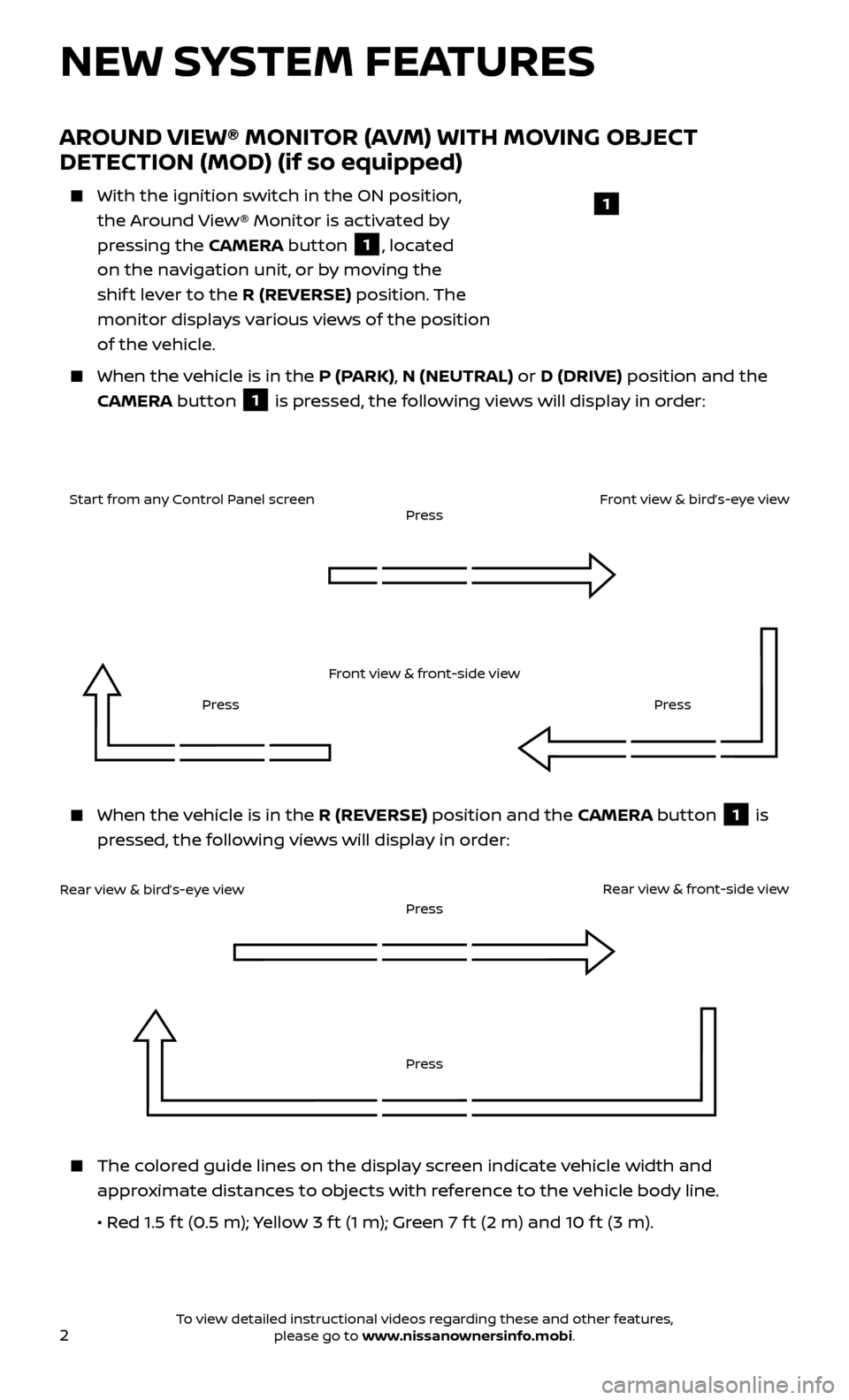
When the v ehicle is in the P (PARK), N (NEUTRAL) or D (DRIVE) position and the
CAMERA button
1 is pressed, the following views will display in order:
NEW SYSTEM FEATURES
When the vehicle is in the R (REVERSE) position and the CAMERA button 1 is
pressed, the following views will display in order:
1
Start from any Control Panel screen
Front view & front-side viewPress
Press Press
Front view & bird’s-eye view
Rear view & bird’s-eye view
PressRear view & front-side viewPress
The colored guide lines on the display screen indicate vehicle width and
approximate distances to objects with reference to the vehicle body line.
• R
ed 1.5 f t (0.5 m); Yellow 3 f t (1 m); Green 7 f t (2 m) and 10 f t (3 m).
To view detailed instructional videos regarding these and other features, please go to www.nissanownersinfo.mobi.
Page 5 of 28
3
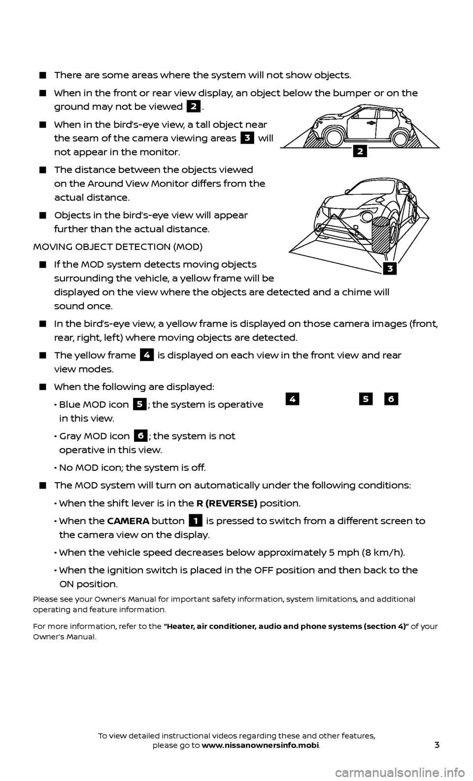
There are some areas where the system will not show objects.
When in the front or rear view display, an object below the bumper or on the
ground may not be viewed
2.
When in the bird’s-eye view, a tall object near
the seam of the camera viewing areas
3 will
not appear in the monitor.
The distanc e between the objects viewed
on the Around View Monitor differs from the
actual distance.
Objects in the bird’s-eye view will appear further than the actual distance.
MOVING OBJECT DETECTION (MOD)
If the MOD system detec ts moving objects
surrounding the vehicle, a yellow frame will be
displayed on the view where the objects are detected and a chime will
sound once.
In the bir d’s-eye view, a yellow frame is displayed on those camera images (front,
rear, right, lef t) where moving objects are detected.
The yellow frame 4 is displayed on each view in the front view and rear
view modes.
When the f ollowing are displayed:
•
Blue MOD ic
on
5; the system is operative
in this view.
•
Gr
ay MOD icon
6; the system is not
operative in this view.
•
No MOD ic
on; the system is off.
The MOD system wil l turn on automatically under the following conditions:
•
When the shif
t lever is in the R (REVERSE) position.
•
When the CAMERA button
1 is pressed to switch from a different screen to
the camera view on the display.
• When the v
ehicle speed decreases below approximately 5 mph (8 km/h).
• When the ignition switch is plac
ed in the OFF position and then back to the
ON position.
Please see your Owner’s Manual for important safety information, system limitations, and additional
operating and feature information.
For more information, refer to the “Heater, air conditioner, audio and phone systems (section 4)” of your
Owner’s Manual.
654
3
2
To view detailed instructional videos regarding these and other features, please go to www.nissanownersinfo.mobi.
Page 11 of 28
9
FIRST DRIVE FEATURES
NISSAN INTELLIGENT KEY® SYSTEM
The Nissan Intelligent Key® system allows you to
lock or unlock the vehicle, open your lif tgate and
start the engine. It is important to make sure the
Intelligent Key is with you (that is, in your pocket
or purse).
The operating range of the Intelligent Key is
within 31.5 in (80 cm) from each
request switch.
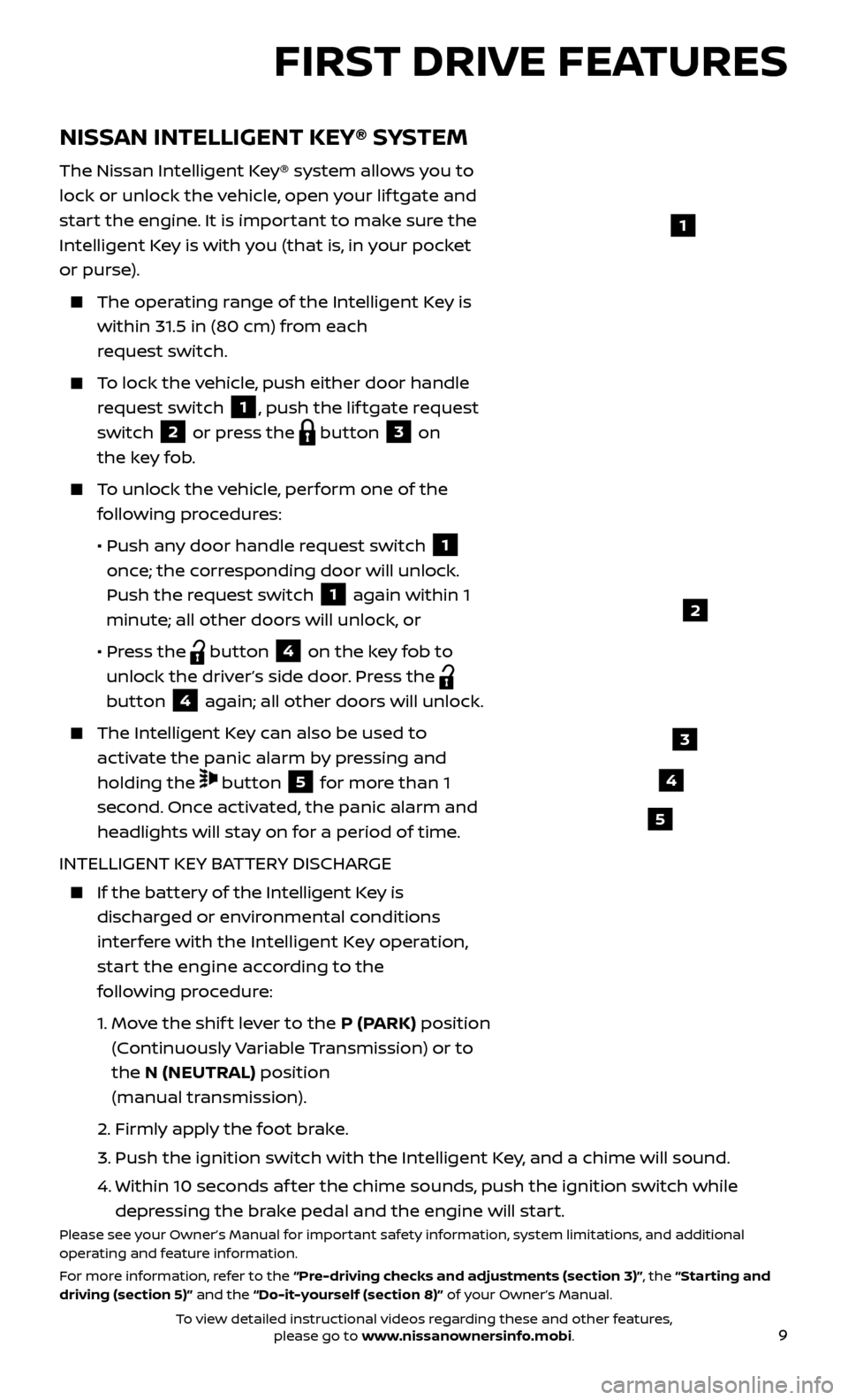
To lock the vehicle, push either door handle request switch
1, push the lif tgate request
switch
2 or press the button 3 on
the key fob.
To unlock the vehicle, perform one of the following procedures:
•
Push an
y door handle request switch
1
once; the corresponding door will unlock.
Push the request switch
1 again within 1
minute; all other doors will unlock, or
•
Pr
ess the
button 4 on the key fob to
unlock the driver’s side door. Press the
button
4 again; all other doors will unlock.
The Intel ligent Key can also be used to
activate the panic alarm by pressing and
holding the
button 5 for more than 1
second. Once activated, the panic alarm and
headlights will stay on for a period of time.
INTELLIGENT KEY BATTERY DISCHARGE
If the bat tery of the Intelligent Key is
discharged or environmental conditions
interfere with the Intelligent Key operation,
start the engine according to the
following procedure:
1.
Mo
ve the shif t lever to the P (PARK) position
(Continuously Variable Transmission) or to
the N (NEUTRAL) position
(manual transmission).
2.
Firmly apply the foot brake.
3.
Push the ignition switch with the Intel
ligent Key, and a chime will sound.
4.
Within 10 sec
onds af ter the chime sounds, push the ignition switch while
depressing the brake pedal and the engine will start.
Please see your Owner’s Manual for important safety information, system limitations, and additional
operating and feature information.
For more information, refer to the “Pre-driving checks and adjustments (section 3)”, the “Starting and
driving (section 5)” and the “Do-it-yourself (section 8)” of your Owner’s Manual.
1
3
4
5
2
To view detailed instructional videos regarding these and other features, please go to www.nissanownersinfo.mobi.
Page 13 of 28

11
STARTING/STOPPING THE ENGINE
CONTINUOUSLY VARIABLE TRANSMISSION
(if so equipped)
It is impor tant to make sure the Nissan
Intelligent Key® is with you (that is, in your
pocket or purse).
Depress the brake pedal.
Move the shif t lever to the P (PARK) position.
Press the ignition switch START/STOP button to start the engine.
MANUAL TRANSMISSION (if so equipped)
Depress the brake pedal.
Move the shif t lever to the N (NEUTRAL) position.
Depress the clutch pedal to the floor while pressing the ignition switch START/STOP button to start the engine.
TURNING THE ENGINE OFF
For a Continuously Variable Transmission, move the shif t lever to the P (PARK) position, apply the parking brake and press the ignition switch
START/STOP button
For a manual transmission, apply the foot brake and place the vehicle in 1st (FIRST) gear, then apply the parking brake and press the ignition switch
START/STOP button.
Please see your Owner’s Manual for important safety information, system limitations, and additional
operating and feature information.
For more information, refer to the “Starting and driving (section 5)” of your Owner’s Manual.
2
1
OUTSIDE MIRROR CONTROL SWITCH
The outside mirr or control switch is located
on the lef t side of the instrument panel.
To select the lef t or right mirror, move the switch
1.
Adjust each mirror to the desired position using the control switch
2.
To prevent accidentally moving the mirror, move the switch
1 to the center
(neutral) position.
Please see your Owner’s Manual for important safety information, system limitations, and additional
operating and feature information.
For more information, refer to the “Pre-driving checks and adjustments (section 3)” of your
Owner’s Manual.
To view detailed instructional videos regarding these and other features, please go to www.nissanownersinfo.mobi.
Page 14 of 28
12
HEADLIGHT CONTROL SWITCH
HEADLIGHT CONTROL
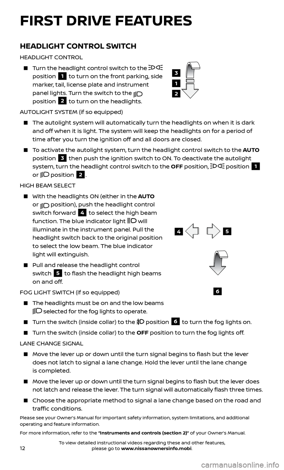
Turn the headlight control switch to the
position
1 to turn on the front parking, side
marker, tail, license plate and instrument
panel lights. Turn the switch to the
position 2 to turn on the headlights.
AUTOLIGHT SYSTEM (if so equipped)
The autolight system wil l automatically turn the headlights on when it is dark
and off when it is light. The system will keep the headlights on for a period of
time af ter you turn the ignition off and all doors are closed.
To activate the autolight system, turn the headlight control switch to the AUTO
position
3 then push the ignition switch to ON. To deactivate the autolight
system, turn the headlight control switch to the OFF position,
position 1
or position 2.
HIGH BEAM SELECT
With the he adlights ON (either in the AUTO
or
position), push the headlight control
switch forward
4 to select the high beam
function. The blue indicator light
will
illuminate in the instrument panel. Pull the
headlight switch back to the original position
to select the low beam. The blue indicator
light will extinguish.
Pull and release the headlight control switch
5 to flash the headlight high beams
on and off.
FOG LIGHT SWITCH (if so equipped)
The headlights must be on and the low beams
selected for the fog lights to operate.
Turn the switch (inside collar) to the position 6 to turn the fog lights on.
Turn the switch (inside collar) to the OFF position to turn the fog lights off.
LANE CHANGE SIGNAL
Move the lever up or down until the turn signal begins to flash but the lever does not latch to signal a lane change. Hold the lever until the lane change
is completed.
Move the lever up or down until the turn signal begins to flash but the lever does not latch and release the lever. The turn signal will automatically flash three times.
Choose the appr opriate method to signal a lane change based on the road and
traffic conditions.
Please see your Owner’s Manual for important safety information, system limitations, and additional
operating and feature information.
For more information, refer to the “Instruments and controls (section 2)” of your Owner’s Manual.
3
1
2
5
6
FIRST DRIVE FEATURES
4
To view detailed instructional videos regarding these and other features, please go to www.nissanownersinfo.mobi.
Page 15 of 28
13
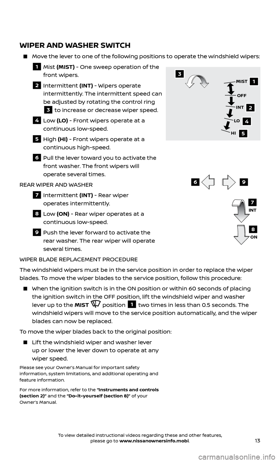
WIPER AND WASHER SWITCH
Move the lever to one of the following positions to operate the windshield wipers:
1 Mist (MIST) - One sweep operation of the
front wipers.
2 Intermittent (INT) - Wipers operate
intermittently. The intermittent speed can
be adjusted by rotating the control ring
3 to increase or decrease wiper speed.
4 Low (LO) - Front wipers operate at a
continuous low-speed.
5 High (HI) - Front wipers operate at a
continuous high-speed.
6 Pull the lever toward you to activate the front washer. The front wipers will
operate several times.
REAR WIPER AND WASHER
7 Intermittent (INT) - Rear wiper
operates intermittently.
8 Low (ON) - Rear wiper operates at a
continuous low-speed.
9 Push the lev er forward to activate the
rear washer. The rear wiper will operate
several times.
WIPER BLADE REPLACEMENT PROCEDURE
The windshield wipers must be in the service position in order to replace the wiper
blades. To move the wiper blades to the service position, follow this procedure:
When the ignition switch is in the ON position or within 60 sec onds of placing
the ignition switch in the OFF position, lif t the windshield wiper and washer
lever up to the MIST
position 1 two times in less than 0.5 seconds. The
windshield wipers will move to the service position automatically, and the wiper
blades can now be replaced.
To move the wiper blades back to the original position:
Lift the windshield wiper and washer lever up or lower the lever down to operate at any
wiper speed.
Please see your Owner’s Manual for important safety
information, system limitations, and additional operating and
feature information.
For more information, refer to the “Instruments and controls
(section 2)” and the “Do-it-yourself (section 8)” of your
Owner’s Manual.
69
1
2
4
5
MIST
OFF
INT
LO
HI3
INT
ON7
8
To view detailed instructional videos regarding these and other features, please go to www.nissanownersinfo.mobi.
Page 20 of 28

18
TRIP COMPUTER
With the ignition switch in the ON position, trip
computer
1 modes can be selected by pushing
the trip computer mode switch
2 on the
instrument panel. The following modes can be
selected in the display:
Trip A – measures the distance of one specific trip.
Trip B – measures the distance of a second specific trip.
Current Fuel Consumption – displays the current fuel consumption.
Distance to Empty (dte ) – displays the estimated distance to empty the vehicle
can be driven before refueling.
Average Fuel Consumption – displays the average fuel consumption since the
last reset.
Torque Vectoring AWD (AWD model) – displays the current amount of torque distributed to each wheel.
Push the trip computer mode switch
2 for approximately 1 second to reset the
currently displayed trip odometer to zero.
Please see your Owner’s Manual for important safety information, system limitations, and additional
operating and feature information.
For more information, refer to the “Instruments and controls (section 2)” of your Owner’s Manual.
SYSTEM GUIDE
TEXT MESSAGING*
This system al lows for sending and receiving
text messages through the vehicle’s interface.
Using predefined or custom messages, send a text to an entry stored in your Bluetooth®
Hands-free Phone System.
Once enabled, the text message, sender and delivery time are shown on the control panel
display when the vehicle speed is less than 5 mph (8 km/h).
Text messages have the option of being read aloud at all vehicle speeds.
Many cellular phones may require special permission to enable text messaging. Check the cellular phone’s screen during Bluetooth® pairing. For some cellular
phones, you need to enable “Notifications” in the cellular phone’s Bluetooth®
menu for text messages to appear on the touch-screen display. For more
information and instructions, refer to your cellular phone’s Owner’s Manual.
Text message integration requires that the celllular phone support Message Access Profile (MAP) for both receiving and sending text messages. Some cellular
phones may not support all text messaging features. Please see
www.NissanUSA.com/bluetooth for compatibility information as well as your
device’s Owner’s Manual.
* Laws in some jurisdictions may restrict the use of “Text-to-Speech”. Some of the applications and features, such as social networking and texting, may also be restricted. Check local regulations for any
requirements before using these features.
Please see your Owner’s Manual for important safety information, system limitations, and additional
operating and feature information.
For more information, refer to the “Heater, air conditioner, audio and phone systems (section 4)” of your
Owner’s Manual.
2
1
To view detailed instructional videos regarding these and other features, please go to www.nissanownersinfo.mobi.