2017 NISSAN JUKE fuel cap
[x] Cancel search: fuel capPage 87 of 416

2-8Instruments and controls
SIC4571
Odometer/twin trip odometer
Odometer/twin trip odometer (Type B) (if
so equipped)
The odometer*1/twin trip odometer*2are
displayed when the ignition switch is in the ON
position.
The odometer records the total distance the
vehicle has been driven.
The twin trip odometer records the distance of
individual trips. Changing the display:
Pushing the reset switch
*3located on the
meter panel changes the display as follows:
TRIP A ?TRIP B ?Trip computer mode ?
TRIP A
For trip computer information, see “Trip compu-
ter” (P.2-13) .
Resetting the trip odometer:
Pushing the reset switch
*3for approximately 1
second resets the trip odometer to zero.
SPA2809
Loose fuel cap warning message
Push the reset switch*Afor more than 1
second to reset the LOOSE FUEL CAP warning
message after the fuel cap has been tightened.
For additional information see “Fuel-filler cap”
(P.3-18) of this manual.
Page 101 of 416

2-22Instruments and controls
Exterior light indicator
This indicator illuminates when the headlight
switch is turned to the AUTO (if so equipped) ,
orposition and the front parking lights,
instrument panel lights, rear combination lights,
license plate lights or headlights are on. The
indicator turns off when these lights are turned
off.
Front fog light indicator light (if so
equipped)
The front fog light indicator light illuminates
when the front fog lights are on. (See “Fog light
switch” (P.2-44) .)
Front passenger air bag status light
The front passenger air bag status light (located
on the center of the instrument panel) will be lit
and the passenger front air bag will be OFF
depending on how the front passenger seat is
being used.
For front passenger air bag status light opera-
tion, see “NISSAN Advanced Air Bag System
(front seats)” (P.1-44) of this manual.
High beam indicator light
This light illuminates when the headlight high
beam is on and goes out when the low beam is
selected.
Malfunction Indicator Light (MIL)
If the malfunction indicator light comes on
steady or blinks while the engine is running, it
may indicate a potential emission control and/or
Continuously Variable Transmission (CVT) mal-
function.
The malfunction indicator light may also illumi-
nate steady if the fuel-filler cap is loose or
missing, or if the vehicle runs out of fuel. Check
to make sure the fuel-filler cap is installed and
closed tightly, and that the vehicle has at least 3
US gallons (11.4 liters) of fuel in the fuel tank.
After a few driving trips, the
light should
turn off if no other potential emission control
system malfunction exists.
If this indicator light remains on for 20 seconds
and then blinks for 10 seconds when the engine
is not running, it indicates that the vehicle is not
ready for an emission control system inspection/
maintenance test. (See “Readiness for Inspec-
tion/Maintenance (I/M) test” (P.10-21) .) Operation:
The malfunction indicator light will come on in
one of two ways:
.
Malfunction indicator light illuminated steady
— An emission control system and/or CVT
malfunction has been detected. Check the
fuel-filler cap if the LOOSE FUEL CAP
warning message is displayed on the twin
trip odometer. If the fuel-filler cap is loose or
missing, tighten or install the cap and
continue to drive the vehicle. The
light
should turn off after a few driving trips. If the
light does not turn off after a few driving
trips, have the vehicle inspected. It is
recommended you visit a NISSAN dealer
for this service. You do not need to have
your vehicle towed to the dealer.
. Malfunction indicator light blinking — An
engine misfire has been detected which may
damage the emission control system.
To reduce or avoid emission control system
damage:
1) Do not drive at speeds above 45 MPH
(72 km/h) .
2) Avoid hard acceleration or deceleration.
3) Avoid steep uphill grades.
4) If possible, reduce the amount of cargo being hauled or towed.
The malfunction indicator light may stop
Page 136 of 416

3 Pre-driving checks and adjustments
Keys ........................................................................\
...................... 3-2Intelligent Keys ..................................................................... 3-2
Doors ........................................................................\
.................... 3-4
Locking with key .................................................................. 3-4
Locking with inside lock knob .......................................... 3-4
Locking with power door lock switch ............................ 3-5
Automatic door locks ......................................................... 3-5
Child safety rear door lock ............................................... 3-6
Intelligent Key system .............................................................. 3-6 Intelligent Key operating range ........................................ 3-8
Door locks/unlocks precaution ........................................ 3-8
Intelligent Key operation .................................................... 3-9
Battery saver system ....................................................... 3-10
Warning lights and audible reminders ........................ 3-10
Troubleshooting guide ..................................................... 3-11
How to use remote keyless entry function ................ 3-12 Hood ........................................................................\
................. 3-15
Liftgate ........................................................................\
............. 3-16
Front side and rear unique parts (NISMO models) ..... 3-17
Fuel-filler door ........................................................................\
3-18
Opening the fuel-filler door ......................................... 3-18
Fuel-filler cap .................................................................. 3-18
Tilt steering column .............................................................. 3-20 Tilt operation ................................................................... 3-20
Sun visors ........................................................................\
........ 3-21
Mirrors ........................................................................\
............. 3-21
Inside mirror ..................................................................... 3-21
Outside mirrors ............................................................... 3-22
Vanity mirror ..................................................................... 3-23
Page 153 of 416

3-18Pre-driving checks and adjustments
SPA2336
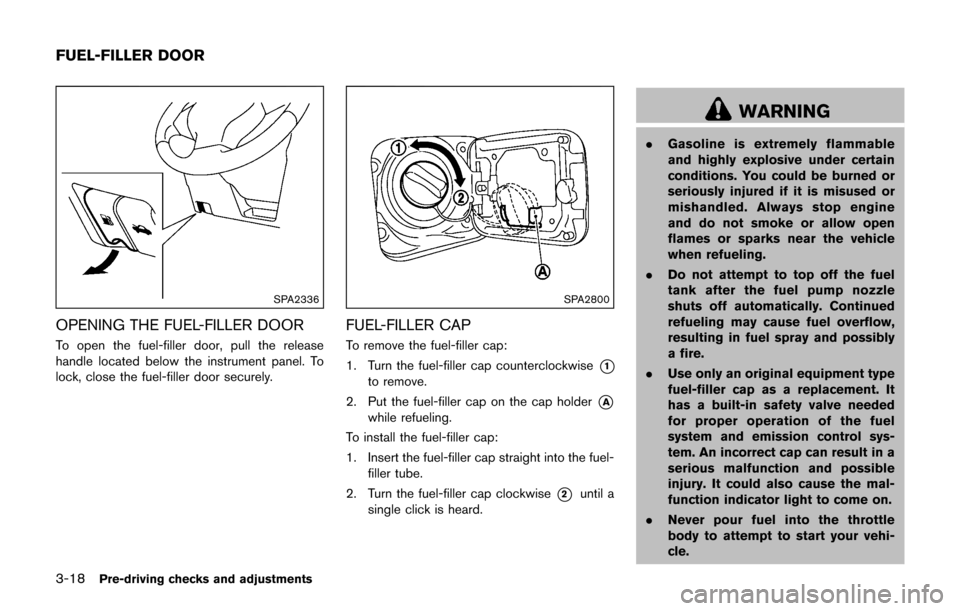
OPENING THE FUEL-FILLER DOOR
To open the fuel-filler door, pull the release
handle located below the instrument panel. To
lock, close the fuel-filler door securely.
SPA2800
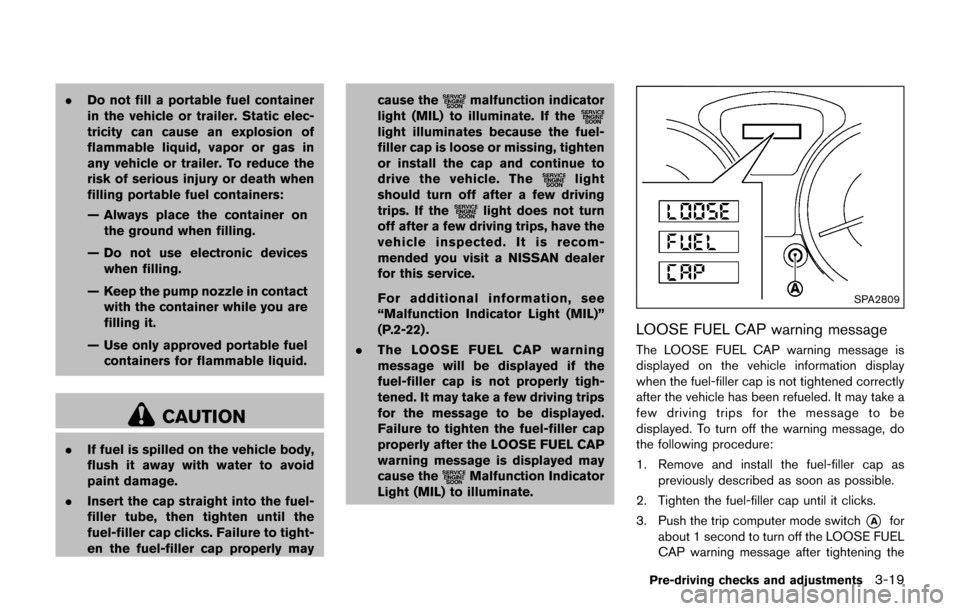
FUEL-FILLER CAP
To remove the fuel-filler cap:
1. Turn the fuel-filler cap counterclockwise
*1
to remove.
2. Put the fuel-filler cap on the cap holder
*A
while refueling.
To install the fuel-filler cap:
1. Insert the fuel-filler cap straight into the fuel- filler tube.
2. Turn the fuel-filler cap clockwise
*2until a
single click is heard.
WARNING
. Gasoline is extremely flammable
and highly explosive under certain
conditions. You could be burned or
seriously injured if it is misused or
mishandled. Always stop engine
and do not smoke or allow open
flames or sparks near the vehicle
when refueling.
. Do not attempt to top off the fuel
tank after the fuel pump nozzle
shuts off automatically. Continued
refueling may cause fuel overflow,
resulting in fuel spray and possibly
a fire.
. Use only an original equipment type
fuel-filler cap as a replacement. It
has a built-in safety valve needed
for proper operation of the fuel
system and emission control sys-
tem. An incorrect cap can result in a
serious malfunction and possible
injury. It could also cause the mal-
function indicator light to come on.
. Never pour fuel into the throttle
body to attempt to start your vehi-
cle.
FUEL-FILLER DOOR
Page 154 of 416

.Do not fill a portable fuel container
in the vehicle or trailer. Static elec-
tricity can cause an explosion of
flammable liquid, vapor or gas in
any vehicle or trailer. To reduce the
risk of serious injury or death when
filling portable fuel containers:
— Always place the container on
the ground when filling.
— Do not use electronic devices when filling.
— Keep the pump nozzle in contact with the container while you are
filling it.
— Use only approved portable fuel containers for flammable liquid.
CAUTION
. If fuel is spilled on the vehicle body,
flush it away with water to avoid
paint damage.
. Insert the cap straight into the fuel-
filler tube, then tighten until the
fuel-filler cap clicks. Failure to tight-
en the fuel-filler cap properly may cause the
malfunction indicator
light (MIL) to illuminate. If the
light illuminates because the fuel-
filler cap is loose or missing, tighten
or install the cap and continue to
drive the vehicle. The
light
should turn off after a few driving
trips. If the
light does not turn
off after a few driving trips, have the
vehicle inspected. It is recom-
mended you visit a NISSAN dealer
for this service.
For additional information, see
“Malfunction Indicator Light (MIL)”
(P.2-22) .
. The LOOSE FUEL CAP warning
message will be displayed if the
fuel-filler cap is not properly tigh-
tened. It may take a few driving trips
for the message to be displayed.
Failure to tighten the fuel-filler cap
properly after the LOOSE FUEL CAP
warning message is displayed may
cause the
Malfunction Indicator
Light (MIL) to illuminate.
SPA2809
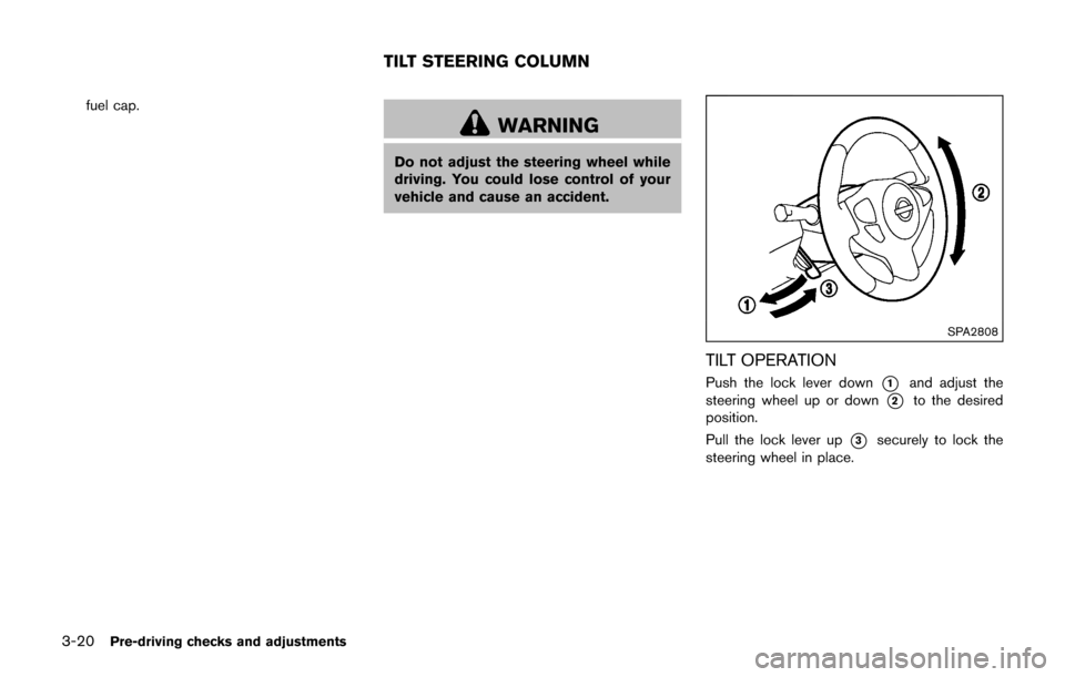
LOOSE FUEL CAP warning message
The LOOSE FUEL CAP warning message is
displayed on the vehicle information display
when the fuel-filler cap is not tightened correctly
after the vehicle has been refueled. It may take a
few driving trips for the message to be
displayed. To turn off the warning message, do
the following procedure:
1. Remove and install the fuel-filler cap as
previously described as soon as possible.
2. Tighten the fuel-filler cap until it clicks.
3. Push the trip computer mode switch
*Afor
about 1 second to turn off the LOOSE FUEL
CAP warning message after tightening the
Pre-driving checks and adjustments3-19
Page 155 of 416

3-20Pre-driving checks and adjustments
fuel cap.
WARNING
Do not adjust the steering wheel while
driving. You could lose control of your
vehicle and cause an accident.
SPA2808
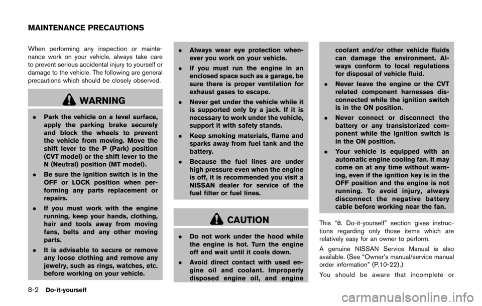
TILT OPERATION
Push the lock lever down*1and adjust the
steering wheel up or down
*2to the desired
position.
Pull the lock lever up
*3securely to lock the
steering wheel in place.
TILT STEERING COLUMN
Page 327 of 416

8-2Do-it-yourself
When performing any inspection or mainte-
nance work on your vehicle, always take care
to prevent serious accidental injury to yourself or
damage to the vehicle. The following are general
precautions which should be closely observed.
WARNING
.Park the vehicle on a level surface,
apply the parking brake securely
and block the wheels to prevent
the vehicle from moving. Move the
shift lever to the P (Park) position
(CVT model) or the shift lever to the
N (Neutral) position (MT model) .
. Be sure the ignition switch is in the
OFF or LOCK position when per-
forming any parts replacement or
repairs.
. If you must work with the engine
running, keep your hands, clothing,
hair and tools away from moving
fans, belts and any other moving
parts.
. It is advisable to secure or remove
any loose clothing and remove any
jewelry, such as rings, watches, etc.
before working on your vehicle. .
Always wear eye protection when-
ever you work on your vehicle.
. If you must run the engine in an
enclosed space such as a garage, be
sure there is proper ventilation for
exhaust gases to escape.
. Never get under the vehicle while it
is supported only by a jack. If it is
necessary to work under the vehicle,
support it with safety stands.
. Keep smoking materials, flame and
sparks away from fuel tank and the
battery.
. Because the fuel lines are under
high pressure even when the engine
is off, it is recommended you visit a
NISSAN dealer for service of the
fuel filter or fuel lines.
CAUTION
.Do not work under the hood while
the engine is hot. Turn the engine
off and wait until it cools down.
. Avoid direct contact with used en-
gine oil and coolant. Improperly
disposed engine oil, and engine coolant and/or other vehicle fluids
can damage the environment. Al-
ways conform to local regulations
for disposal of vehicle fluid.
. Never leave the engine or the CVT
related component harnesses dis-
connected while the ignition switch
is in the ON position.
. Never connect or disconnect the
battery or any transistorized com-
ponent while the ignition switch is
in the ON position.
. Your vehicle is equipped with an
automatic engine cooling fan. It may
come on at any time without warn-
ing, even if the ignition key is in the
OFF position and the engine is not
running. To avoid injury, always
disconnect the negative battery
cable before working near the fan.
This “8. Do-it-yourself” section gives instruc-
tions regarding only those items which are
relatively easy for an owner to perform.
A genuine NISSAN Service Manual is also
available. (See “Owner’s manual/service manual
order information” (P.10-22) .)
You should be aware that incomplete or
MAINTENANCE PRECAUTIONS
Page 372 of 416

The following descriptions are provided to give
you a better understanding of the scheduled
maintenance items that should be regularly
checked or replaced. The maintenance sche-
dule indicates at which mileage/time intervals
each item requires service.
In addition to scheduled maintenance, your
vehicle requires that some items be checked
during normal day-to-day operation. Refer to
“General maintenance” (P.9-2) .
Items marked with “*” are recommended by
NISSAN for reliable vehicle operation. You are
not required to perform maintenance on these
items in order to maintain the warranties which
come with your vehicle. Other maintenance
items and intervals are required.
When applicable, additional information can be
found in the “8. Do-it yourself” section of this
manual.
NOTE:
NISSAN does not advocate the use of non-
OEM approved aftermarket flushing sys-
tems and strongly advises against per-
forming these services on a NISSAN
product. Many of the aftermarket flushing
systems use non-OEM approved chemicals
or solvents, the use of which has not been
validated by NISSAN.For recommended fuel, lubricants, fluids,
grease, and refrigerant, refer to
“Capaci-
ties and recommended fluids/lubricants”
(P.10-2) of this manual.
EMISSION CONTROL SYSTEM MAIN-
TENANCE
Drive belts*:
Check engine drive belts for wear, fraying or
cracking and for proper tension. Replace any
damaged drive belts.
Engine air filter:
Replace at specified intervals. When driving for
prolonged periods in dusty conditions, check/
replace the filter more frequently.
Engine coolant*:
Replace coolant at the specified interval. When
adding or replacing coolant, be sure to use only
Genuine NISSAN Long Life Antifreeze/Coolant
(blue) or equivalent with the proper mixture.
(Refer to “Engine cooling system” (P.8-4) to
determine the proper mixture for your area.)
NOTE:
Mixing any other type of coolant or the use
of non-distilled water may reduce the
recommended service interval of the cool-
ant. Engine oil and oil filter:
Replace engine oil and oil filter at the specified
intervals. For recommended oil grade and vis-
cosity refer to “Capacities and recommended
fluids/lubricants” (P.10-2) .
Engine valve clearance*:
Inspect only if valve noise increases.
Adjust valve clearance if necessary.
Evaporative emissions control vapor
lines*:
Check vapor lines for leaks or looseness.
Tighten connections or replace parts as neces-
sary.
Fuel filter
Periodic maintenance is not required (in-tank
type filter) .
Fuel lines*:
Check the fuel hoses, piping and connections
for leaks, looseness, or deterioration. Tighten
connections or replace parts as necessary.
Spark plugs:
Replace at specified intervals. Install new plugs
of the type as originally equipped.
Maintenance and schedules9-5
EXPLANATION OF SCHEDULED
MAINTENANCE ITEMS