Page 14 of 478
1. Power moonroof (if so equipped)(P. 2-52)
2. Map lights (if so equipped) (P. 2-53)
3. Sun visors (P. 3-14)
4. Rearview mirror (P. 3-15) Homelink® universal transceiver
(if so equipped) (P. 2-55)
5. Glove box (P. 2-40)
6. Shift lever (P. 5-14)
7. Cup holders (P. 2-40)
8. Console box (P. 2-40)
9. Spare tire tools location (P. 6-3)
Refer to the page number indicated in pa-
rentheses for operating details.
LII2483
PASSENGER COMPARTMENT
Illustrated table of contents0-5
Page 15 of 478
1. Vents (P. 4-16)
2. Headlight/fog light (if so equipped)/turnsignal switch (P. 2-29)
3. Steering wheel switch for audio control
(if so equipped) (P. 4-72)
Bluetooth® Hands-Free Phone System
(if so equipped) (P. 4-69, 4-89)
4. Driver supplemental air bag (P. 1-71) Horn (P. 2-33)
5. Meters and gauges (P. 2-3) Warning and indicator lights (P. 2-14)
6. Cruise control main/set switches
(if so equipped) (P. 5-21)
7. Wiper and washer switch (P. 2-27)
8. Storage (P. 2-40)
9. Audio system (if so equipped) (P. 4-36)
10. Front passenger supplemental air bag
(P. 1-71)
11. Upper and lower glove box (P. 2-44)
12. Passenger air bag status light (P. 1-80)
13. USB connection port (if so equipped)
(P. 4-36)
AUX input (if so equipped) (P. 4-36)
14. Power outlets (P. 2-39)
LII2484
INSTRUMENT PANEL
0-6Illustrated table of contents
Page 100 of 478

all of the information, cautions and warn-
ings in this manual still apply and must be
followed.
The driver supplemental front-impact air bag is
located in the center of the steering wheel. The
front passenger supplemental front-impact air
bag is mounted in the dashboard above the glove
box. The front air bags are designed to inflate in
higher severity frontal collisions, although they
may inflate if the forces in another type of collision
are similar to those of a higher severity frontal
impact. They may not inflate in certain frontal
collisions. Vehicle damage (or lack of it) is not
always an indication of proper front air bag sys-
tem operation.
The NISSAN Advanced Air Bag System monitors
information from the crash zone sensor, the Air
bag Control Unit (ACU) , seat belt buckle sen-
sors, occupant classification sensor (pressure
sensor) and passenger seat belt tension sensor.
Inflator operation is based on the severity of a
collision and seat belt usage for the driver. For the
front passenger, it additionally monitors the
weight of an occupant or object on the seat and
seat belt tension. Based on information from the
sensors, only one front air bag may inflate in a
crash, depending on the crash severity and
whether the front occupants are belted or un-
belted. Additionally, the front passenger air bag
may be automatically turned off under some con-ditions, depending on the weight detected on the
front passenger seat and how the seat belt is
used. If the front passenger air bag is OFF, the
front passenger air bag status light will be illumi-
nated (if the seat is unoccupied, the light will not
be illuminated, but the air bag will be off) . For
additional information, refer to “Front passenger
air bag and status light” in this section. One front
air bag inflating does not indicate improper per-
formance of the system.
If you have any questions about your air bag
system, it is recommended that you visit a
NISSAN dealer to obtain information about the
system. If you are considering modification of
your vehicle due to a disability, you may also
contact NISSAN. Contact information is con-
tained in the front of this Owner’s Manual.
When a front air bag inflates, a fairly loud noise
may be heard, followed by the release of smoke.
This smoke is not harmful and does not indicate a
fire. Care should be taken to not inhale it, as it may
cause irritation and choking. Those with a history
of a breathing condition should get fresh air
promptly.
Front air bags, along with the use of seat belts,
help to cushion the impact force on the face and
chest of the front occupants. They can help save
lives and reduce serious injuries. However, an
inflating front air bag may cause facial abrasionsor other injuries. Front air bags do not provide
restraint to the lower body.
Even with NISSAN Advanced Air Bags, seat
belts should be correctly worn and the driver and
front passenger seated upright as far as practical
away from the steering wheel or instrument
panel. The front air bags inflate quickly in order to
help protect the front occupants. Because of this,
the force of the front air bag inflating can increase
the risk of injury if the occupant is too close to, or
is against, the front air bag module during infla-
tion.
The front air bags deflate quickly after a collision.
The front air bags operate only when the
ignition switch is in the ON or START posi-
tion.
After placing the ignition switch in the ON
position, the supplemental air bag warning
light illuminates. The supplemental air bag
warning light will turn off after about 7 sec-
onds if the system is operational.
Safety—Seats, seat belts and supplemental restraint system1-79
Page 110 of 478
 .........")
Storage trays................................. 2-43
Glove box .................................... 2-44
Console box .................................. 2-45
Sunglasses holder (if so equipped) ..............2-45
Cup holders .................................. 2-46
Roof rack (if so equipped) ......................2-48
Windows ........................................ 2-49
Power windows (if so equipped) ................2-49
Manual windows (if so equipped) ................2-51
Rear sliding window (if so equipped) ............2-52
Moonroof (if so equipped) ......................... 2-52
Power moonroof ............................... 2-52Interior lights
..................................... 2-53
Map lights (if so equipped) .....................2-55
HomeLink® universal transceiver (if so equipped) ....2-55
Programming HomeLink® ......................2-56
Programming HomeLink® for Canadian
customers and gate openers ....................2-57
Operating the HomeLink® Universal
Transceiver ................................... 2-57
Programming trouble-diagnosis .................2-58
Clearing the programmed information ............2-58
Reprogramming a single HomeLink® button ......2-58
If your vehicle is stolen ......................... 2-58
Page 111 of 478
1. Vents (P. 4-16)
2. Headlight/fog light (if so equipped)/turnsignal switch (P. 2-29)
3. Steering wheel switch for audio control
(if so equipped) (P. 4-72)
Bluetooth® Hands-Free Phone System
(if so equipped) (P. 4-69, 4-89)
4. Driver supplemental air bag (P. 1-71) Horn (P. 2-33)
5. Meters and gauges (P. 2-3) Warning and indicator lights (P. 2-14)
6. Cruise control main/set switches (if so
equipped) (P. 5-21)
7. Wiper and washer switch (P. 2-27)
8. Storage (P. 2-40)
9. Audio system (if so equipped) (P. 4-36)
10. Front passenger supplemental air bag
(P. 1-71)
11. Upper and lower glove box (P. 2-44)
12. Passenger air bag status light (P. 1-80)
13. USB connection port (if so equipped)
(P. 4-36)
AUX input (if so equipped) (P. 4-36)
14. Power outlets (P. 2-39)
LII2484
INSTRUMENT PANEL
2-2Instruments and controls
Page 153 of 478
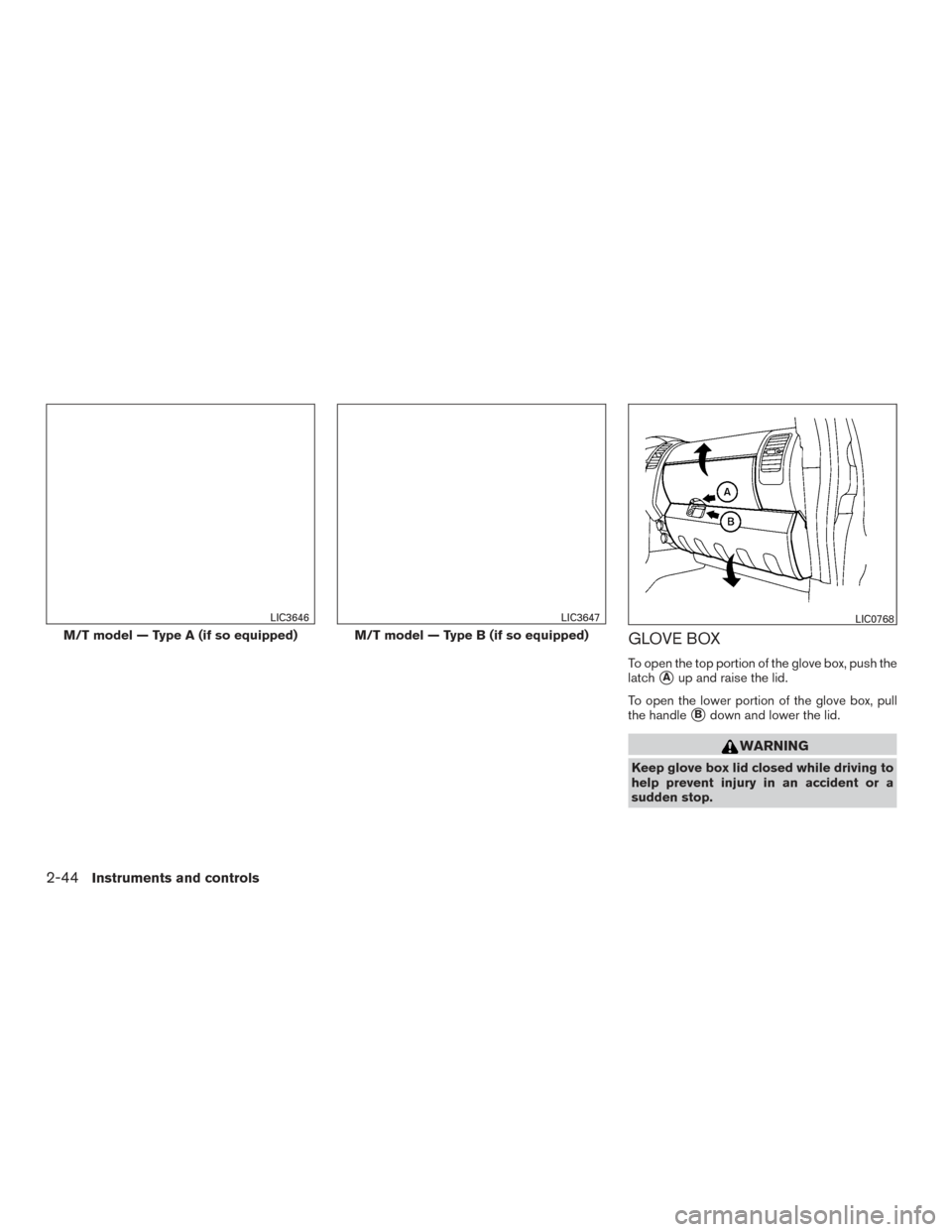
GLOVE BOX
To open the top portion of the glove box, push the
latch
�Aup and raise the lid.
To open the lower portion of the glove box, pull
the handle
�Bdown and lower the lid.
WARNING
Keep glove box lid closed while driving to
help prevent injury in an accident or a
sudden stop.
M/T model — Type A (if so equipped)
LIC3646
M/T model — Type B (if so equipped)
LIC3647LIC0768
2-44Instruments and controls
Page 188 of 478

Before removing the tailgate disconnect the rear
camera by performing the following:1. Open the tailgate to access the rear camera connector bracket
�1lo")
Disconnecting the rear camera (if so
equipped)
Before removing the tailgate disconnect the rear
camera by performing the following:1. Open the tailgate to access the rear camera connector bracket
�1located on the rear
sill.
2. Remove the connector bracket
�2from the
sill by pressing the locking tab inward, in the
direction shown, while pulling the bracket
apart. 3. Disconnect the chassis wiring harness
�3
by pressing inward on the locking tab, in the
direction shown, while pulling the connec-
tors apart. Hold the connector firmly to pre-
vent the connector in the chassis harness
from falling into the sill.
4. Take the chassis plug and bracket from the glove box and connect them to the chassis
wiring harness to avoid contamination to the
terminals which will lead to malfunction of
the rear camera.
5. Insert the bracket back into the sill. 6. Take the tailgate plug from the glove box and
connect it to the tailgate wiring harness to
avoid contamination which will lead to mal-
function of the rear camera.
7. Remove the tailgate. For additional informa- tion, refer to “Removing the tailgate” in this
section.
LPD2097
Pre-driving checks and adjustments3-19
Page 190 of 478

Before closing the tailgate reconnect the rear
camera by performing the following:1. After attaching the rear tailgate to the truck, keep the tailgate open")
Connecting the rear camera (if so
equipped)
Before closing the tailgate reconnect the rear
camera by performing the following:1. After attaching the rear tailgate to the truck, keep the tailgate open and check that the
tailgate harness is not hanging below the
tailgate.
2. Remove the connector bracket
�2from the
sill by pressing the locking tab inward, in the
direction shown, while pulling the bracket
apart. 3. Disconnect the chassis plug and bracket
from the chassis wiring harness
�3. Keep
the connector and bracket in a safe place
such as the glove box.
4. Disconnect the tailgate plug from the tail- gate wiring harness. Keep the tailgate plug
in a safe place such as the glove box.
5. Connect the tailgate wiring harness to the chassis wiring harness.
6. Securely fix the rear camera connector bracket
�1to the rear sill.
7. Close the tailgate securely.
Locking the tailgate
To lock the tailgate, turn the key toward the pas-
senger side of the vehicle
�1. To unlock, turn the
key toward the driver side
�2.
LPD2097LPD0272
Pre-driving checks and adjustments3-21
(P. 2-52)
2. Map lights (if so equipped) (P. 2-53)
3. Sun visors (P. 3-14)
4. Rearview mirror (P. 3-15) Homelink® universal transceiver
(if so equipped) (P. 2-55)
5.")

2. Headlight/fog light (if so equipped)/turnsignal switch (P. 2-29)
3. Steering wheel switch for audio control
(if so equipped) (P. 4-72)
Bluetooth® Hands-Free Phone System
(if so")

2. Headlight/fog light (if so equipped)/turnsignal switch (P. 2-29)
3. Steering wheel switch for audio control
(if so equipped) (P. 4-72)
Bluetooth® Hands-Free Phone System
(if so")