Page 15 of 614

0-8Illustrated table of contents
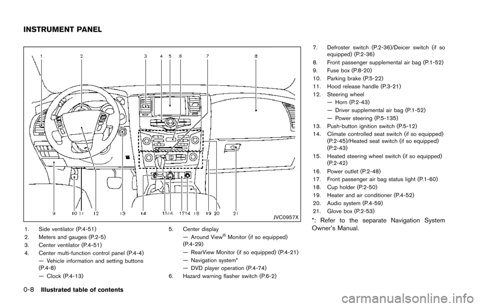
JVC0957X
1. Side ventilator (P.4-51)
2. Meters and gauges (P.2-5)
3. Center ventilator (P.4-51)
4. Center multi-function control panel (P.4-4)— Vehicle information and setting buttons
(P.4-8)
— Clock (P.4-13) 5. Center display
— Around View�ŠMonitor (if so equipped)
(P.4-29)
— RearView Monitor (if so equipped) (P.4-21)
— Navigation system*
— DVD player operation (P.4-74)
6. Hazard warning flasher switch (P.6-2) 7. Defroster switch (P.2-36)/Deicer switch (if so
equipped) (P.2-36)
8. Front passenger supplemental air bag (P.1-52)
9. Fuse box (P.8-20)
10. Parking brake (P.5-22)
11. Hood release handle (P.3-21)
12. Steering wheel — Horn (P.2-43)
— Driver supplemental air bag (P.1-52)
— Power steering (P.5-135)
13. Push-button ignition switch (P.5-12)
14. Climate controlled seat switch (if so equipped) (P.2-45)/Heated seat switch (if so equipped)
(P.2-43)
15. Heated steering wheel switch (if so equipped) (P.2-42)
16. Power outlet (P.2-48)
17. Front passenger air bag status light (P.1-60)
18. Cup holder (P.2-50)
19. Heater and air conditioner (P.4-52)
20. Audio system (P.4-59)
21. Glove box (P.2-53)
*: Refer to the separate Navigation System
Owner’s Manual.
INSTRUMENT PANEL
Page 93 of 614
2-4Instruments and controls
JVC0957X
1. Side ventilator
2. Meters and gauges
3. Center ventilator
4. Center multi-function control panel— Vehicle information and setting buttons
— Clock 5. Center display
— Around View�ŠMonitor (if so equipped)
— RearView Monitor (if so equipped)
— Navigation system*
— DVD player operation
6. Hazard warning flasher switch
7. Defroster switch/Deicer switch (if so equipped) 8. Front passenger supplemental air bag
9. Fuse box
10. Parking brake
11. Hood release handle
12. Steering wheel
— Horn
— Driver supplemental air bag
— Power steering
13. Push-button ignition switch
14. Climate controlled seat switch (if so equipped)/ Heated seat switch (if so equipped)
15. Heated steering wheel switch (if so equipped)
16. Power outlet
17. Front passenger air bag status light
18. Cup holder
19. Heater and air conditioner
20. Audio system
21. Glove box
*: Refer to the separate Navigation System
Owner’s Manual.
INSTRUMENT PANEL
Page 124 of 614

even though the amount of the rainfall
is small.
. Be sure to turn off the rain-sensing
auto wiper system when you use a car
wash.
. Using genuine wiper blades is recom-
mended for proper operation of the
rain-sensing auto wiper system. (See
“Windshield wiper blades” (P.8-16) for
wiper blade replacement.)
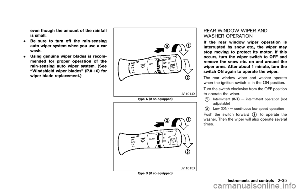
JVI1014XType A (if so equipped)
JVI1015XType B (if so equipped)
REAR WINDOW WIPER AND
WASHER OPERATION
If the rear window wiper operation is
interrupted by snow etc., the wiper may
stop moving to protect its motor. If this
occurs, turn the wiper switch to OFF and
remove the snow etc. on and around the
wiper arms. After about 1 minute, turn the
switch ON again to operate the wiper.
The rear window wiper and washer operate
when the ignition switch is in the ON position.
Turn the switch clockwise from the OFF position
to operate the wiper.
*1Intermittent (INT) — intermittent operation (not
adjustable)
*2Low (ON) — continuous low speed operation
Push the switch forward*3to operate the
washer. Then the wiper will also operate several
times.
Instruments and controls2-35
Page 189 of 614

3-28Pre-driving checks and adjustments
may cause theMalfunction
Indicator Light (MIL) to illuminate.
Turn the cap counterclockwise to remove. To
tighten, turn the cap clockwise until a single
click is heard.
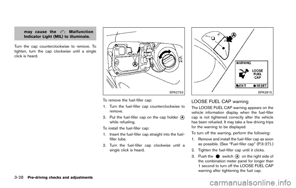
SPA2753
To remove the fuel-filler cap:
1. Turn the fuel-filler cap counterclockwise to remove.
2. Put the fuel-filler cap on the cap holder
*Awhile refueling.
To install the fuel-filler cap:
1. Insert the fuel-filler cap straight into the fuel- filler tube.
2. Turn the fuel-filler cap clockwise until a single click is heard.
SPA2815
LOOSE FUEL CAP warning
The LOOSE FUEL CAP warning appears on the
vehicle information display when the fuel-filler
cap is not tightened correctly after the vehicle
has been refueled. It may take a few driving trips
for the warning to be displayed.
To turn off the warning, perform the following:
1. Remove and install the fuel-filler cap as soonas possible. (See “Fuel-filler cap” (P.3-27) .)
2. Tighten the fuel-filler cap until it clicks.
3. Push the
switch*Aon the right side of
the combination meter panel for longer than
1 second to turn off the LOOSE FUEL CAP
warning after tightening the fuel cap.
Page 213 of 614
4-16Monitor, heater, air conditioner, audio, phone and voice recognition systems
SAA3008
Others settings
The Others settings display will appear when
pushing the SETTING button and selecting the
“Others” key.
Available setting items may vary depending on
models and specifications.
The following items are available:
.Display
. Comfort
. Clock
. Language & Units
. Voice Recognition .
Camera
. Image Viewer
SAA2486
Display settings
The display as illustrated will appear when
pushing the SETTING button and selecting the
“Others” key, and then selecting the “Display”
key.
Display Adjustment:
To adjust the display settings, select the “Dis-
play Adjustment” key. The following settings are
available.
.Display
To turn off the screen, push the ENTER button
and turn the “Display” indicator off. The other
method is to push and hold the
OFF button
for more than 2 seconds.
Page 215 of 614

4-18Monitor, heater, air conditioner, audio, phone and voice recognition systems
Lift Steering Wheel on Exit (if so
equipped):
When this item is turned to ON, the steering
wheel moves upward for easy exit if the ignition
switch is in the LOCK position and the driver’s
door is opened. After getting into the vehicle and
pushing the ignition switch to the ACC position,
the steering wheel moves to the previous
position.
Slide Driver Seat Back on Exit (if so
equipped):
When this item is turned to ON, the driver’s seat
moves backward for easy exit if the ignition
switch is in the OFF position and the driver’s
door is opened. After getting into the vehicle and
pushing the ignition switch to the ACC position,
the driver’s seat moves to the previous position.
Return All Settings to Default:
Select this item and then select “YES” to return
all settings to the default.
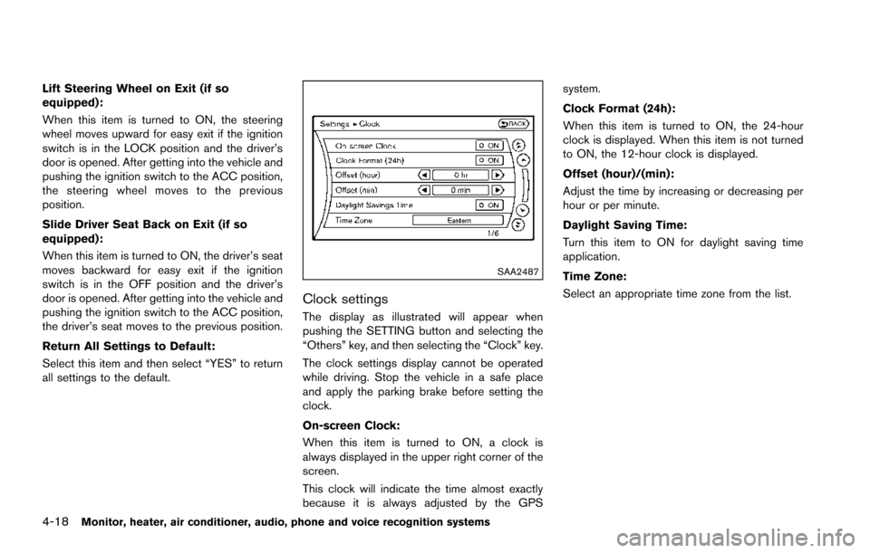
SAA2487
Clock settings
The display as illustrated will appear when
pushing the SETTING button and selecting the
“Others” key, and then selecting the “Clock” key.
The clock settings display cannot be operated
while driving. Stop the vehicle in a safe place
and apply the parking brake before setting the
clock.
On-screen Clock:
When this item is turned to ON, a clock is
always displayed in the upper right corner of the
screen.
This clock will indicate the time almost exactly
because it is always adjusted by the GPSsystem.
Clock Format (24h):
When this item is turned to ON, the 24-hour
clock is displayed. When this item is not turned
to ON, the 12-hour clock is displayed.
Offset (hour)/(min):
Adjust the time by increasing or decreasing per
hour or per minute.
Daylight Saving Time:
Turn this item to ON for daylight saving time
application.
Time Zone:
Select an appropriate time zone from the list.
Page 489 of 614
6-6In case of emergency
SCE0915
5. Securely screw to connect the T-shapedend of the jack rod and two extension bars
*1as illustrated.
6. Fit the square end of the jack rod into the square hole of the wheel nut wrench to form
a handle
*2. 7. Locate the oval opening above the middle of
the rear bumper.
8. Place the T-shaped end of the jack rod through the opening and direct it towards
the spare wheel winch assembly, located
directly above the spare wheel.
SCE0916
CAUTION
Do not insert the jack rod straight as it
is designed to be inserted at an angle
as shown.
9. Seat the T-shaped end of the jack rod into the T-shaped opening of the spare wheel
winch. Apply pressure to keep the jack rod
engaged in the spare wheel winch and turn
the jack rod counterclockwise to lower the
spare wheel.
Page 492 of 614
SCE0876
2. Loosen each wheel nut one or two turns byturning counterclockwise with the wheel nut
wrench. Do not remove the wheel nuts
until the tire is off the ground.
NCE130
3. Install the assembled jack rod into the jack
as shown.
4. Carefully raise the vehicle until the clearance between the tire and ground is achieved.
5. To lift the vehicle, securely hold the jack lever and rod with both hands and turn the jack
lever.
NOTE:
Before jacking up the vehicle, make sure
the ignition switch is placed in the OFF
position. If the vehicle is lifted up with the
engine running, the auto-leveling suspen-
sion will become disabled after 120 sec-
onds. To reset the auto-leveling
In case of emergency6-9