2017 NISSAN ARMADA steering
[x] Cancel search: steeringPage 190 of 614
WARNING
.Do not adjust the steering wheel
while driving. You could lose control
of your vehicle and cause an acci-
dent.
. Do not adjust the steering wheel
any closer to you than is necessary
for proper steering operation and
comfort. The driver’s air bag inflates
with great force. If you are unrest-
rained, leaning forward, sitting side-
ways or out of position in any way,
you are at greater risk of injury or
death in a crash. You may also
receive serious or fatal injuries from
the air bag if you are up against it
when it inflates. Always sit back
against the seatback and as far
away as practical from the steering
wheel. Always use the seat belts.
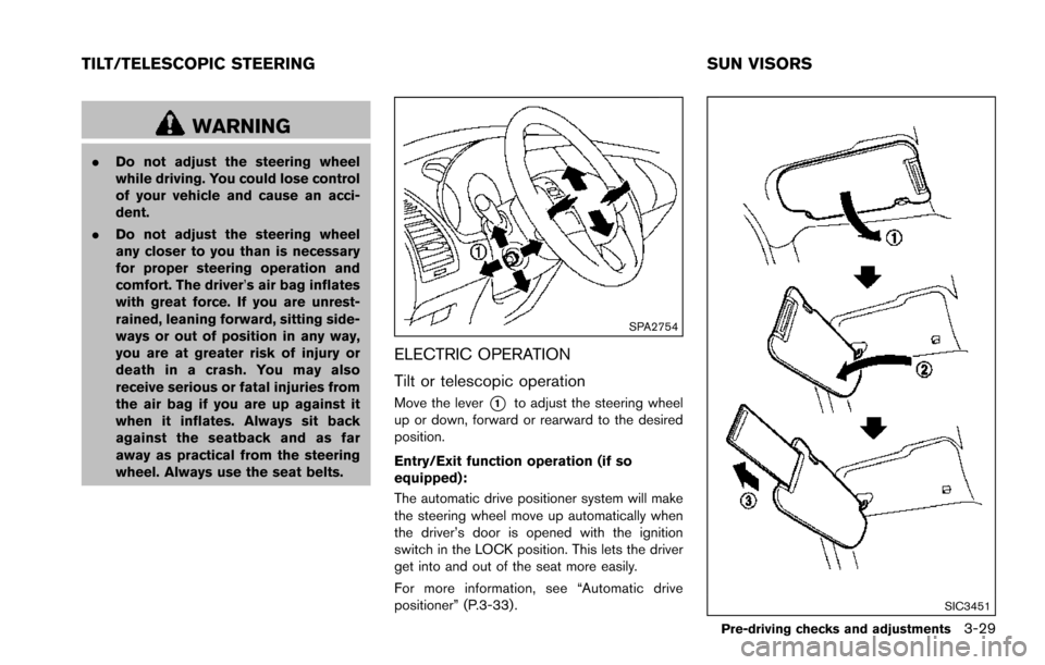
SPA2754
ELECTRIC OPERATION
Tilt or telescopic operation
Move the lever*1to adjust the steering wheel
up or down, forward or rearward to the desired
position.
Entry/Exit function operation (if so
equipped):
The automatic drive positioner system will make
the steering wheel move up automatically when
the driver’s door is opened with the ignition
switch in the LOCK position. This lets the driver
get into and out of the seat more easily.
For more information, see “Automatic drive
positioner” (P.3-33).
SIC3451
Pre-driving checks and adjustments3-29
TILT/TELESCOPIC STEERING SUN VISORS
Page 194 of 614
4. The outside mirror surfaces move down-ward.
When one of the following conditions has
occurred, the outside mirror surfaces will return
to their original positions.
. The shift lever is moved to any position other
than R (Reverse) .
. The outside mirror control switch is set to
the center position.
. The ignition switch is placed in the OFF
position.
Automatic anti-glare (if so equipped)
The outside rearview mirrors are designed so
that its automatically change reflection accord-
ing to the intensity of the headlights of the
vehicle following you.
The anti-glare system will be automatically
turned on when the ignition switch is placed in
the ON position.SIC4448
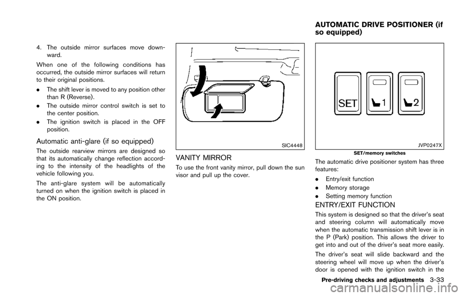
VANITY MIRROR
To use the front vanity mirror, pull down the sun
visor and pull up the cover.
JVP0247XSET/memory switches
The automatic drive positioner system has three
features:
.Entry/exit function
. Memory storage
. Setting memory function
ENTRY/EXIT FUNCTION
This system is designed so that the driver’s seat
and steering column will automatically move
when the automatic transmission shift lever is in
the P (Park) position. This allows the driver to
get into and out of the driver’s seat more easily.
The driver’s seat will slide backward and the
steering wheel will move up when the driver’s
door is opened with the ignition switch in the
Pre-driving checks and adjustments3-33
AUTOMATIC DRIVE POSITIONER (if
so equipped)
Page 195 of 614
3-34Pre-driving checks and adjustments
LOCK position.
The driver’s seat and steering wheel will return
to the previous positions when the ignition
switch is pushed to the ACC position.
The driver’s seat will not return to the previous
positions if the seat or steering adjusting switch
is operated when the seat is at the exit position.
Cancel or activate entry/exit function
The shift lever must be in the P (Park) position
with the ignition switch in the OFF position.
The entry/exit function can be activated or
canceled by pressing and holding the SET
switch for more than 10 seconds.
The entry/exit function can also be activated or
canceled if the “Lift Steering Wheel on Exit” key
or “Slide Driver Seat Back on Exit” key is turned
to ON or OFF in the “Comfort” settings. (See
“How to use SETTING button” (P.4-13) .)
Initialize entry/exit function
If the battery cable is disconnected, or if the fuse
opens, the entry/exit function will not work
though this function was set on before. In such
a case, after connecting the battery or replacing
with a new fuse, open and close the driver’s
door more than two times after the ignition
switch is turned from the ON position to the
LOCK position. The entry/exit function will beactivated.
MEMORY STORAGE
Two positions for the driver’s seat, steering
column and outside mirrors can be stored in the
automatic drive positioner memory. Follow these
procedures to use the memory system.
1. Move the shift lever to the P (Park) position.
2. Adjust the driver’s seat, steering column and
outside mirrors to the desired positions by
manually operating each adjusting switch.
For additional information, see “Seats” (P.1-
2) and “Tilt/telescopic steering” (P.3-29)
and “Outside mirrors” (P.3-31) .
3. Push the SET switch and, within 5 seconds, push the memory switch (1 or 2) fully for at
least 1 second.
The indicator light for the pushed memory
switch will stay on for approximately 5
seconds after pushing the switch.
When the memory is stored in the memory
switch (1 or 2) , a buzzer will sound.
If memory is stored in the same memory
switch, the previous memory will be deleted.
Linking Intelligent Key to a stored mem-
ory position
The Intelligent Key can be linked to a stored
memory position with the following procedure.
1. Follow the steps for storing a memoryposition.
2. While the indicator light for the memory switch being set is illuminated for 5 sec-
onds, push the
button on the Intelligent
Key. If the indicator light blinks, the Intelli-
gent Key is linked to that memory setting.
Push the ignition switch to the OFF position, and
then push the
button on the Intelligent Key.
The driver’s seat, steering wheel and outside
mirrors will move to the memorized position.
Confirming memory storage
. Push the ignition switch to the ON position
and push the SET switch. If the main
memory has not been stored, the indicator
light will come on for approximately 0.5
second. When the memory has stored in
position, the indicator light will stay on for
approximately 5 seconds.
. If the battery cable is disconnected, or if the
fuse opens, the memory will be canceled. In
this case, reset the desired position using
the previous procedure.
Page 196 of 614
.If optional Intelligent Keys are added to your
vehicle, the memory storage procedure to
switch 1 or 2 and linking Intelligent Key
procedure to a stored memory position
should be performed again for each Intelli-
gent Key. For additional Intelligent Key
information, see “Keys” (P.3-2) .
Selecting the memorized position
1. Move the shift lever to the P (Park) position.
2. Use one of the following methods to move
the driver’s seat, the outside mirrors and the
steering wheel.
.Within 45 seconds of opening thedriver’s door, push the memory switch
(1 or 2) fully for at least 1 second.
The driver’s seat, steering column and
outside mirrors will move to the memorized
position or to the exit position when the
entry/exit function is set to active with the
indicator light flashing, and then the light will
stay on for approximately 5 seconds.
SETTING MEMORY FUNCTION
The status of the following settings can be linked
to the Intelligent Key and the memorized settings
can be available for each Intelligent Key.
. Air conditioner system .
Navigation system
. Audio system
To use the memory function, lock the doors with
the Intelligent Key that is linked to the settings.
To enable the memorized settings:
1. Carry the Intelligent Key that is linked to the settings, and unlock the doors by pushing
the driver’s door handle request switch or
“UNLOCK”
button on the Intelligent
Key.
2. Place the ignition switch in the ON position. “Connection with the key has been done”
will be displayed on the screen and the
memorized settings are available (only when
a new Intelligent Key is used) .
SYSTEM OPERATION
The automatic drive positioner system will not
work or will stop operating under the following
conditions:
.When the vehicle speed is above 4 MPH (7
km/h) .
. When the adjusting switch for the driver’s
seat and steering column is turned on while
the automatic drive positioner is operating.
. When the memory switch 1 or 2 is not
pushed for at least 1 second. .
When the seat, steering column and outside
mirrors have already been moved to the
memorized position.
. When no position is stored in the memory
switch.
. When the engine is started while moving the
automatic drive positioner.
. When the AT shift lever is moved from the P
(Park) position to any other position. (How-
ever, it will not be canceled if the switch is
pushed while the seat and steering column
are returning to the previous positions
(entry/exit function) .)
. When the driver’s door remains open for
more than 45 seconds and the ignition
switch is not in the ON position.
Pre-driving checks and adjustments3-35
Page 199 of 614
Linking Intelligent Key (if so equipped) ...................... 4-58
In-cabin microfilter ........................................................... 4-58
Servicing air conditioner ................................................. 4-58
Audio system ........................................................................\
... 4-59
Audio operation precautions ......................................... 4-59
FM-AM-SAT radio with Compact Disc
(CD) player ........................................................................\
4-70
DVD (Digital Versatile Disc) player operation ........... 4-74
USB (Universal Serial Bus) connection port ............ 4-77
Bluetooth
�Šstreaming audio .......................................... 4-81
iPod�Šplayer operation .................................................... 4-86
Front auxiliary input jacks (if so equipped) ................ 4-88
CD/DVD/USB memory care and cleaning ................ 4-90
Steering-wheel-mounted controls for audio .............. 4-91
Antenna ........................................................................\
....... 4-92
DVD Entertainment System (if so equipped) ................. 4-92 Licenses ........................................................................\
...... 4-93
System components ........................................................ 4-93
Before operating DVD Entertainment System .......... 4-99
Playing Digital Versatile Disc (DVD)/USB .............. 4-100
Operating tips ................................................................ 4-105
Care and maintenance ................................................. 4-105 Car phone or CB radio ..................................................... 4-106
Bluetooth
�ŠHands-Free Phone System ........................ 4-106
Regulatory information ............................................... 4-108
Voice commands ......................................................... 4-108
Control buttons ............................................................ 4-108
Connecting procedure ............................................... 4-109
Phone selection ........................................................... 4-109
Quick Dial ..................................................................... 4-109
Making a call ................................................................ 4-112
Receiving a call ........................................................... 4-113
During a call ................................................................. 4-113
Phone setting ............................................................... 4-114
Troubleshooting guide ............................................... 4-116
NISSAN Voice Recognition system .............................. 4-117
NISSAN Voice Recognition Standard Mode ....... 4-117
Using the system ........................................................ 4-120
NISSAN Voice Recognition Alternate
Command Mode ......................................................... 4-130
Using the system ........................................................ 4-138
Troubleshooting guide ............................................... 4-143
Page 204 of 614
.Delete:
Deletes the last character that has been
input with one touch. Push and hold the
button to delete all of the characters.
. OK:
Completes character inputs.
Touch screen maintenance
If you clean the display screen, use a dry, soft
cloth. If additional cleaning is necessary, use a
small amount of neutral detergent with a soft
cloth. Never spray the screen with water or
detergent. Dampen the cloth first, and then wipe
the screen.
JVH1394X
MENU OPTIONS
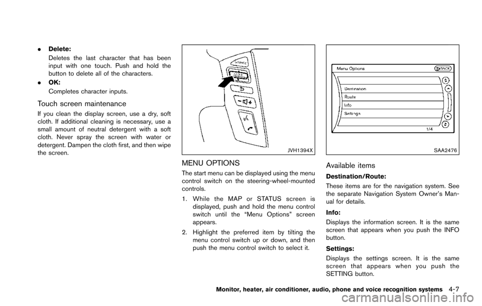
The start menu can be displayed using the menu
control switch on the steering-wheel-mounted
controls.
1. While the MAP or STATUS screen is
displayed, push and hold the menu control
switch until the “Menu Options” screen
appears.
2. Highlight the preferred item by tilting the menu control switch up or down, and then
push the menu control switch to select it.
SAA2476
Available items
Destination/Route:
These items are for the navigation system. See
the separate Navigation System Owner’s Man-
ual for details.
Info:
Displays the information screen. It is the same
screen that appears when you push the INFO
button.
Settings:
Displays the settings screen. It is the same
screen that appears when you push the
SETTING button.
Monitor, heater, air conditioner, audio, phone and voice recognition systems4-7
Page 215 of 614
4-18Monitor, heater, air conditioner, audio, phone and voice recognition systems
Lift Steering Wheel on Exit (if so
equipped):
When this item is turned to ON, the steering
wheel moves upward for easy exit if the ignition
switch is in the LOCK position and the driver’s
door is opened. After getting into the vehicle and
pushing the ignition switch to the ACC position,
the steering wheel moves to the previous
position.
Slide Driver Seat Back on Exit (if so
equipped):
When this item is turned to ON, the driver’s seat
moves backward for easy exit if the ignition
switch is in the OFF position and the driver’s
door is opened. After getting into the vehicle and
pushing the ignition switch to the ACC position,
the driver’s seat moves to the previous position.
Return All Settings to Default:
Select this item and then select “YES” to return
all settings to the default.
SAA2487
Clock settings
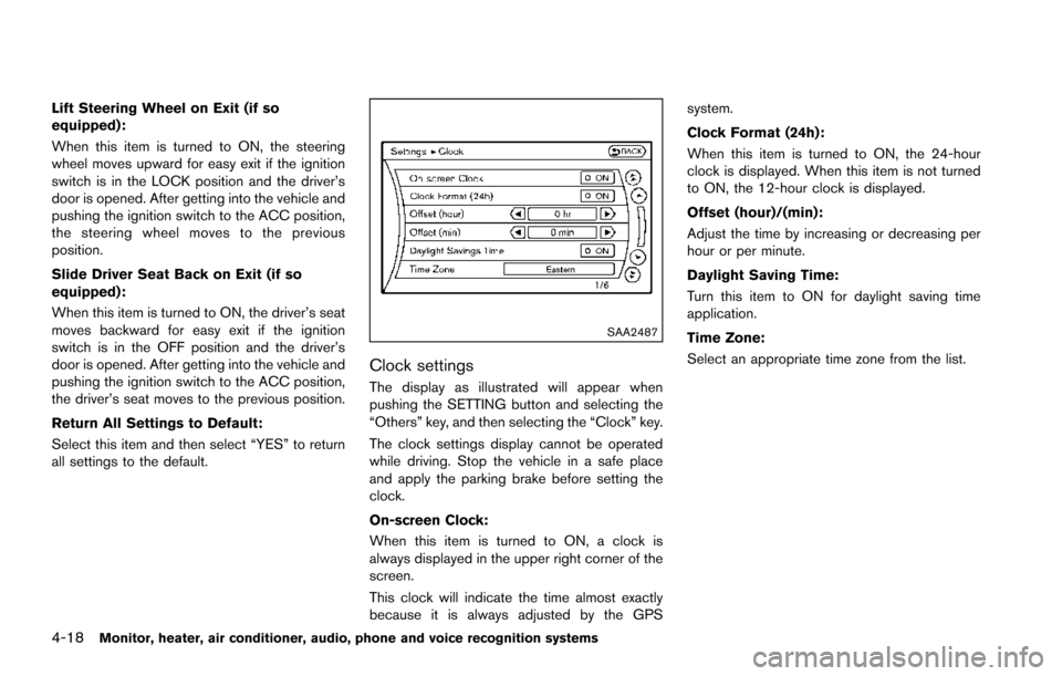
The display as illustrated will appear when
pushing the SETTING button and selecting the
“Others” key, and then selecting the “Clock” key.
The clock settings display cannot be operated
while driving. Stop the vehicle in a safe place
and apply the parking brake before setting the
clock.
On-screen Clock:
When this item is turned to ON, a clock is
always displayed in the upper right corner of the
screen.
This clock will indicate the time almost exactly
because it is always adjusted by the GPSsystem.
Clock Format (24h):
When this item is turned to ON, the 24-hour
clock is displayed. When this item is not turned
to ON, the 12-hour clock is displayed.
Offset (hour)/(min):
Adjust the time by increasing or decreasing per
hour or per minute.
Daylight Saving Time:
Turn this item to ON for daylight saving time
application.
Time Zone:
Select an appropriate time zone from the list.
Page 220 of 614
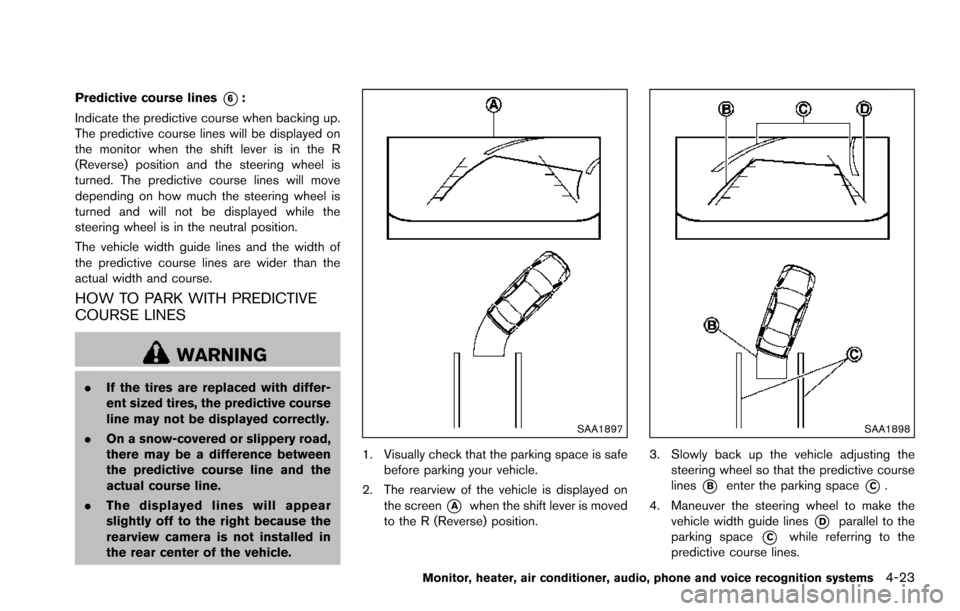
Predictive course lines*6:
Indicate the predictive course when backing up.
The predictive course lines will be displayed on
the monitor when the shift lever is in the R
(Reverse) position and the steering wheel is
turned. The predictive course lines will move
depending on how much the steering wheel is
turned and will not be displayed while the
steering wheel is in the neutral position.
The vehicle width guide lines and the width of
the predictive course lines are wider than the
actual width and course.
HOW TO PARK WITH PREDICTIVE
COURSE LINES
WARNING
. If the tires are replaced with differ-
ent sized tires, the predictive course
line may not be displayed correctly.
. On a snow-covered or slippery road,
there may be a difference between
the predictive course line and the
actual course line.
. The displayed lines will appear
slightly off to the right because the
rearview camera is not installed in
the rear center of the vehicle.
SAA1897
1. Visually check that the parking space is safe
before parking your vehicle.
2. The rearview of the vehicle is displayed on the screen
*Awhen the shift lever is moved
to the R (Reverse) position.
SAA1898
3. Slowly back up the vehicle adjusting the steering wheel so that the predictive course
lines
*Benter the parking space*C.
4. Maneuver the steering wheel to make the vehicle width guide lines
*Dparallel to the
parking space
*Cwhile referring to the
predictive course lines.
Monitor, heater, air conditioner, audio, phone and voice recognition systems4-23