2017 NISSAN ARMADA steering
[x] Cancel search: steeringPage 83 of 614
1-64Safety — seats, seat belts and supplemental restraint system
.A child restraint or other object pressing
against the rear of the seatback.
. A rear passenger pushing or pulling on the
back of the front passenger seat.
. Forcing the front seat or seatback against an
object on the seat or floor behind it.
. An object placed under the front passenger
seat.
. An object placed between the seat cushion
and center console.
If the vehicle is moving, please come to a stop
when it is safe to do so. Check and correct any
of the above conditions. Restart the vehicle and
wait 1 minute.
NOTE:
A system check will be performed during
which the front passenger air bag status
light will remain lit for about 7 seconds
initially.
If the light is still OFF after this, the small adult,
child or child restraint should be repositioned in
the rear seat and it is recommended that the
vehicle be checked by a NISSAN dealer as soon
as possible.Other supplemental front-impact air bag
precautions
WARNING
. Do not place any objects on the
steering wheel pad or on the instru-
ment panel. Also, do not place any
objects between any occupant and
the steering wheel or instrument
panel. Such objects may become
dangerous projectiles and cause
injury if the front air bags inflate.
. Do not place objects with sharp
edges on the seat. Also, do not
place heavy objects on the seat that
will leave permanent impressions in
the seat. Such objects can damage
the seat or occupant classification
sensors (weight sensors) . This can
affect the operation of the air bag
system and result in serious perso-
nal injury.
. Do not use water or acidic cleaners
(hot steam cleaners) on the seat.
This can damage the seat or occu-
pant classification sensors. This can
also affect the operation of the air
bag system and result in serious personal injury.
. Immediately after inflation, several
front air bag system components
will be hot. Do not touch them; you
may severely burn yourself.
. No unauthorized changes should be
made to any components or wiring
of the supplemental air bag system.
This is to prevent accidental infla-
tion of the supplemental air bag or
damage to the supplemental air bag
system.
. Do not make unauthorized changes
to your vehicle’s electrical system,
suspension system or front end
structure. This could affect proper
operation of the front air bag sys-
tem.
. Tampering with the air bag system
may result in serious personal in-
jury. Tampering includes changes to
the steering wheel and the instru-
ment panel assembly by placing
material over the steering wheel
pad and above the instrument panel
or by installing additional trim ma-
terial around the air bag system.
Page 90 of 614
2 Instruments and controls
Cockpit ........................................................................\
................ 2-3
Instrument panel ........................................................................\
2-4
Meters and gauges ................................................................... 2-5Speedometer and odometer ............................................ 2-6
Tachometer ........................................................................\
... 2-7
Engine coolant temperature gauge ................................ 2-7
Fuel gauge ........................................................................\
.... 2-8
Engine oil pressure gauge ................................................ 2-8
Voltmeter ........................................................................\
........ 2-9
Meter/ring illumination and needle sweep .................... 2-9
Warning lights, indicator lights and
audible reminders ................................................................... 2-10 Checking lights ................................................................. 2-11
Warning lights ................................................................... 2-11
Indicator lights ................................................................... 2-17
Audible reminders ............................................................ 2-20
Vehicle information display .................................................. 2-20 Operational indicators ..................................................... 2-23
Maintenance indicators ................................................... 2-26
Trip computer .................................................................... 2-27
Security systems .................................................................... 2-30 Vehicle Security System ................................................. 2-30
NISSAN Vehicle Immobilizer System .......................... 2-31 Wiper and washer switch ................................................... 2-32
Windshield wiper and washer operation ................. 2-33
Rain-sensing auto wiper system (if
so equipped) ................................................................... 2-34
Rear window wiper and washer operation .............. 2-35
Rear window and outside mirror (if so equipped)
defroster switch ..................................................................... 2-36
Windshield deicer switch (if so equipped) .................... 2-36
Headlight and turn signal switch ....................................... 2-37 Headlight switch ............................................................ 2-37
Instrument brightness control ..................................... 2-40
Turn signal switch .......................................................... 2-41
Fog light switch (if so equipped) .............................. 2-42
Heated steering wheel (if so equipped) ......................... 2-42
Horn ........................................................................\
.................. 2-43
Heated seats ........................................................................\
.. 2-43 Front (if so equipped) ................................................... 2-44
Rear (if so equipped) .................................................... 2-44
Climate controlled seats (if so equipped) ...................... 2-45
Warning systems switch (if so equipped) ...................... 2-46
Sonar system OFF switch (if so equipped) ................... 2-47
SNOW mode switch ............................................................ 2-47
TOW mode switch ................................................................ 2-47
Page 92 of 614
JVC0956X
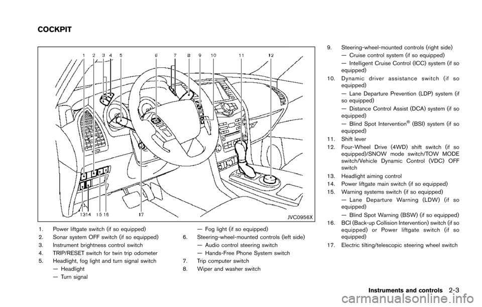
1. Power liftgate switch (if so equipped)
2. Sonar system OFF switch (if so equipped)
3. Instrument brightness control switch
4. TRIP/RESET switch for twin trip odometer
5. Headlight, fog light and turn signal switch— Headlight
— Turn signal — Fog light (if so equipped)
6. Steering-wheel-mounted controls (left side) — Audio control steering switch
— Hands-Free Phone System switch
7. Trip computer switch
8. Wiper and washer switch 9. Steering-wheel-mounted controls (right side)
— Cruise control system (if so equipped)
— Intelligent Cruise Control (ICC) system (if so
equipped)
10. Dynamic driver assistance switch (if so equipped)
— Lane Departure Prevention (LDP) system (if
so equipped)
— Distance Control Assist (DCA) system (if so
equipped)
— Blind Spot Intervention
�Š(BSI) system (if so
equipped)
11. Shift lever
12. Four-Wheel Drive (4WD) shift switch (if so equipped)/SNOW mode switch/TOW MODE
switch/Vehicle Dynamic Control (VDC) OFF
switch
13. Headlight aiming control
14. Power liftgate main switch (if so equipped)
15. Warning systems switch (if so equipped) — Lane Departure Warning (LDW) (if so
equipped)
— Blind Spot Warning (BSW) (if so equipped)
16. BCI (Back-up Collision Intervention) switch (if so equipped) or Power liftgate switch (if so
equipped)
17. Electric tilting/telescopic steering wheel switch
Instruments and controls2-3
COCKPIT
Page 93 of 614
2-4Instruments and controls
JVC0957X
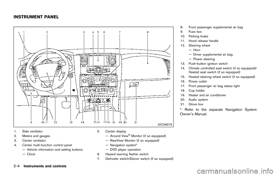
1. Side ventilator
2. Meters and gauges
3. Center ventilator
4. Center multi-function control panel— Vehicle information and setting buttons
— Clock 5. Center display
— Around View�ŠMonitor (if so equipped)
— RearView Monitor (if so equipped)
— Navigation system*
— DVD player operation
6. Hazard warning flasher switch
7. Defroster switch/Deicer switch (if so equipped) 8. Front passenger supplemental air bag
9. Fuse box
10. Parking brake
11. Hood release handle
12. Steering wheel
— Horn
— Driver supplemental air bag
— Power steering
13. Push-button ignition switch
14. Climate controlled seat switch (if so equipped)/ Heated seat switch (if so equipped)
15. Heated steering wheel switch (if so equipped)
16. Power outlet
17. Front passenger air bag status light
18. Cup holder
19. Heater and air conditioner
20. Audio system
21. Glove box
*: Refer to the separate Navigation System
Owner’s Manual.
INSTRUMENT PANEL
Page 104 of 614
Low tire pressure warning light
Your vehicle is equipped with a Tire Pressure
Monitoring System (TPMS) that monitors the tire
pressure of all tires except the spare.
The low tire pressure warning light warns of low
tire pressure or indicates that the TPMS is not
functioning properly.
After the ignition switch is placed in the ON
position, this light illuminates for about 1 second
and turns off.
Low tire pressure warning:
If the vehicle is being driven with low tire
pressure, the warning light will illuminate. A
CHECK TIRE PRESSURE warning also appears
in the vehicle information display. If you select
the tire pressure information in the display, the
LOW PRESSURE information will be displayed.
The tire pressure for each tire will also be
displayed.
When the low tire pressure warning light
illuminates, you should stop and adjust the tire
pressure to the recommended COLD tire
pressure shown on the Tire and Loading
Information label. The low tire pressure warning
light does not automatically turn off when the tire
pressure is adjusted. After the tire is inflated to
the recommended pressure, the vehicle must be
driven at speeds above 16 MPH (25 km/h) toactivate the TPMS and turn off the low tire
pressure warning light. Use a tire pressure
gauge to check the tire pressure.
The CHECK TIRE PRESSURE warning appears
each time the ignition switch is placed in the ON
position as long as the low tire pressure warning
light remains illuminated.
For additional information, see “Vehicle informa-
tion display” (P.2-20) , “Tire Pressure Monitoring
System (TPMS)” (P.5-5) and “Tire Pressure
Monitoring System (TPMS) ” (P.6-3) .
TPMS malfunction:
If the TPMS is not functioning properly, the low
tire pressure warning light will flash for approxi-
mately 1 minute when the ignition switch is
placed in the ON position. The light will remain
on after 1 minute. Have the system checked. It is
recommended you visit a NISSAN dealer for this
service. The CHECK TIRE PRESSURE warning
does not appear if the low tire pressure warning
light illuminates to indicate a TPMS malfunction.
For additional information, see “Tire Pressure
Monitoring System (TPMS)” (P.5-5) .
WARNING
.
If the light does not illuminate with
the ignition switch placed in the ON position, have the vehicle checked
as soon as possible. It is recom-
mended you visit a NISSAN dealer
for this service.
. If the light illuminates or LOW
PRESSURE information is displayed
on the monitor screen while driving,
avoid sudden steering maneuvers or
abrupt braking, reduce vehicle
speed, pull off the road to a safe
location and stop the vehicle as
soon as possible. Driving with un-
der-inflated tires may permanently
damage the tires and increase the
likelihood of tire failure. Serious
vehicle damage could occur and
may lead to an accident and could
result in serious personal injury.
Check the tire pressure for all four
tires. Adjust the tire pressure to the
recommended COLD tire pressure
shown on the Tire and Loading
Information label to turn the low
tire pressure warning light OFF. If
the light still illuminates while driv-
ing after adjusting the tire pressure,
a tire may be flat or the TPMS may
be malfunctioning. If you have a flat
tire, replace it with a spare tire as
soon as possible. If no tire is flat
Instruments and controls2-15
Page 131 of 614
2-42Instruments and controls
SIC3672
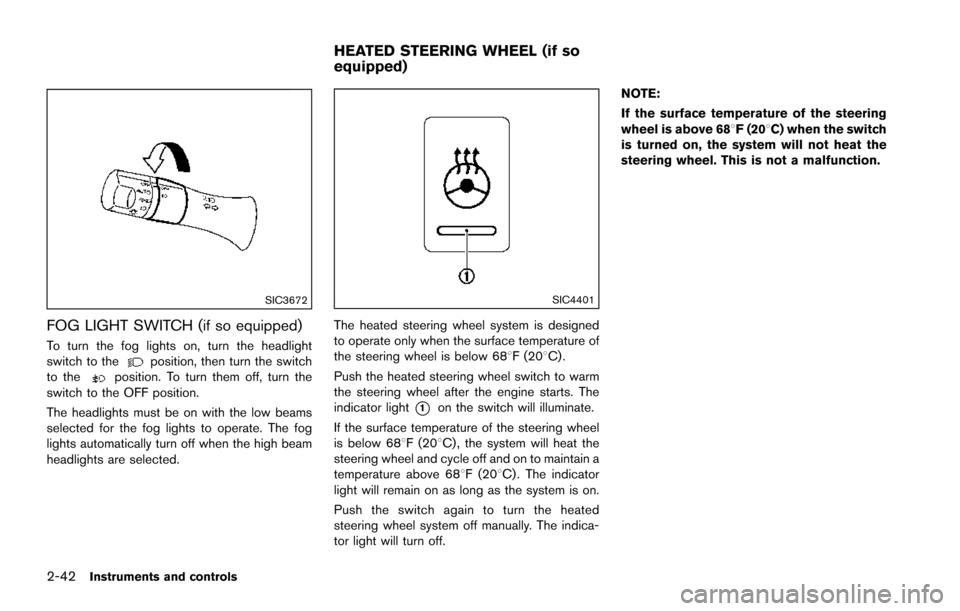
FOG LIGHT SWITCH (if so equipped)
To turn the fog lights on, turn the headlight
switch to theposition, then turn the switch
to theposition. To turn them off, turn the
switch to the OFF position.
The headlights must be on with the low beams
selected for the fog lights to operate. The fog
lights automatically turn off when the high beam
headlights are selected.
SIC4401
The heated steering wheel system is designed
to operate only when the surface temperature of
the steering wheel is below 688F (208C) .
Push the heated steering wheel switch to warm
the steering wheel after the engine starts. The
indicator light
*1on the switch will illuminate.
If the surface temperature of the steering wheel
is below 688F (208C) , the system will heat the
steering wheel and cycle off and on to maintain a
temperature above 688F (208C) . The indicator
light will remain on as long as the system is on.
Push the switch again to turn the heated
steering wheel system off manually. The indica-
tor light will turn off. NOTE:
If the surface temperature of the steering
wheel is above 688F (208C) when the switch
is turned on, the system will not heat the
steering wheel. This is not a malfunction.
HEATED STEERING WHEEL (if so
equipped)
Page 132 of 614
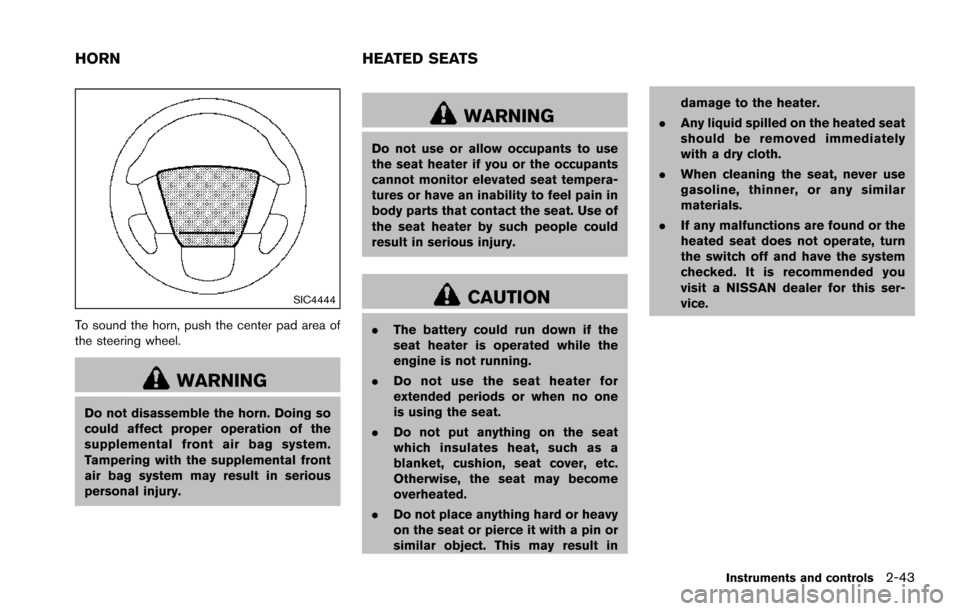
SIC4444
To sound the horn, push the center pad area of
the steering wheel.
WARNING
Do not disassemble the horn. Doing so
could affect proper operation of the
supplemental front air bag system.
Tampering with the supplemental front
air bag system may result in serious
personal injury.
WARNING
Do not use or allow occupants to use
the seat heater if you or the occupants
cannot monitor elevated seat tempera-
tures or have an inability to feel pain in
body parts that contact the seat. Use of
the seat heater by such people could
result in serious injury.
CAUTION
.The battery could run down if the
seat heater is operated while the
engine is not running.
. Do not use the seat heater for
extended periods or when no one
is using the seat.
. Do not put anything on the seat
which insulates heat, such as a
blanket, cushion, seat cover, etc.
Otherwise, the seat may become
overheated.
. Do not place anything hard or heavy
on the seat or pierce it with a pin or
similar object. This may result in damage to the heater.
. Any liquid spilled on the heated seat
should be removed immediately
with a dry cloth.
. When cleaning the seat, never use
gasoline, thinner, or any similar
materials.
. If any malfunctions are found or the
heated seat does not operate, turn
the switch off and have the system
checked. It is recommended you
visit a NISSAN dealer for this ser-
vice.
Instruments and controls2-43
HORN HEATED SEATS
Page 162 of 614
3 Pre-driving checks and adjustments
Keys ........................................................................\
...................... 3-2Intelligent Key ....................................................................... 3-2
Valet hand-off ....................................................................... 3-4
Doors ........................................................................\
.................... 3-4 Locking with mechanical key ............................................ 3-4
Opening and closing windows with the
mechanical key ..................................................................... 3-5
Locking with inside lock knob .......................................... 3-5
Locking with power door lock switch ............................ 3-5
Automatic door locks ......................................................... 3-6
Child safety rear door lock .............................................. 3-6
Intelligent Key system .............................................................. 3-7 Intelligent Key operating range ........................................ 3-9
Door locks/unlocks precaution ........................................ 3-9
Intelligent Key operation ................................................. 3-10
Battery saver system ....................................................... 3-12
Warning signals ................................................................ 3-12
Troubleshooting guide ..................................................... 3-13
Remote keyless entry system ............................................. 3-15 How to use remote keyless entry system .................. 3-16
Remote engine start (if so equipped) .............................. 3-19 Remote engine start operating range ......................... 3-19
Remote starting the engine ........................................... 3-19
Extending engine run time ............................................. 3-20 Canceling a remote start ............................................. 3-20
Conditions the remote engine start will
not work ........................................................................\
.... 3-20
Hood ........................................................................\
................. 3-21
Liftgate ........................................................................\
............. 3-22 Operating manual liftgate ............................................. 3-22
Operating power liftgate (if so equipped) ............... 3-22
Auto closure ................................................................... 3-25
Liftgate release lever ..................................................... 3-26
Fuel-filler door ........................................................................\
3-26
Opening the fuel-filler door ......................................... 3-26
Fuel-filler cap .................................................................. 3-27
Tilt/telescopic steering ......................................................... 3-29
Electric operation ........................................................... 3-29
Sun visors ........................................................................\
........ 3-29
Mirrors ........................................................................\
.............. 3-30
Inside mirror ..................................................................... 3-30
Outside mirrors ............................................................... 3-31
Vanity mirror ..................................................................... 3-33
Automatic drive positioner (if so equipped) ................... 3-33
Entry/exit function .......................................................... 3-33
Memory storage .............................................................. 3-34
Setting memory function .............................................. 3-35
System operation ........................................................... 3-35