2017 NISSAN ARMADA check engine light
[x] Cancel search: check engine lightPage 188 of 614
.Push the power door lock switch to the
UNLOCK position.
To lock, close the fuel-filler door securely and
lock all doors by operating the door handle
request switch, the LOCK button on the
Intelligent Key, the mechanical key or the power
door lock switch.
FUEL-FILLER CAP
WARNING
. Gasoline is extremely flammable
and highly explosive under certain
conditions. You could be burned or
seriously injured if it is misused or
mishandled. Always stop engine
and do not smoke or allow open
flames or sparks near the vehicle
when refueling.
. Do not attempt to top off the fuel
tank after the fuel pump nozzle
shuts off automatically. Continued
refueling may cause fuel overflow,
resulting in fuel spray and possibly
a fire.
. Use only an original equipment type
fuel-filler cap as a replacement. It
has a built-in safety valve needed
for proper operation of the fuel system and emission control sys-
tem. An incorrect cap can result in a
serious malfunction and possible
injury. It could also cause the mal-
function indicator light to come on.
. Never pour fuel into the throttle
body to attempt to start your vehi-
cle.
. Do not fill a portable fuel container
in the vehicle or trailer. Static elec-
tricity can cause an explosion of
flammable liquid, vapor or gas in
any vehicle or trailer. To reduce the
risk of serious injury or death when
filling portable fuel containers:
— Always place the container on
the ground when filling.
— Do not use electronic devices when filling.
— Keep the pump nozzle in contact with the container while you are
filling it.
— Use only approved portable fuel containers for flammable liquid.
CAUTION
. If fuel is spilled on the vehicle body,
flush it away with water to avoid
paint damage.
. Insert the cap straight into the fuel-
filler tube, then tighten until the
fuel-filler cap clicks. Failure to tight-
en the fuel-filler cap properly may
cause the
malfunction indicator
light (MIL) to illuminate. If the
light illuminates because the fuel-
filler cap is loose or missing, tighten
or install the cap and continue to
drive the vehicle. The
light
should turn off after a few driving
trips. If the
light does not turn
off after a few driving trips, have the
vehicle inspected. It is recom-
mended you visit a NISSAN dealer
for this service.
. The LOOSE FUEL CAP warning will
appear if the fuel-filler cap is not
properly tightened. It may take a few
driving trips for the message to be
displayed. Failure to tighten the
fuel-filler cap properly after the
LOOSE FUEL CAP warning appears
Pre-driving checks and adjustments3-27
Page 196 of 614
.If optional Intelligent Keys are added to your
vehicle, the memory storage procedure to
switch 1 or 2 and linking Intelligent Key
procedure to a stored memory position
should be performed again for each Intelli-
gent Key. For additional Intelligent Key
information, see “Keys” (P.3-2) .
Selecting the memorized position
1. Move the shift lever to the P (Park) position.
2. Use one of the following methods to move
the driver’s seat, the outside mirrors and the
steering wheel.
.Within 45 seconds of opening thedriver’s door, push the memory switch
(1 or 2) fully for at least 1 second.
The driver’s seat, steering column and
outside mirrors will move to the memorized
position or to the exit position when the
entry/exit function is set to active with the
indicator light flashing, and then the light will
stay on for approximately 5 seconds.
SETTING MEMORY FUNCTION
The status of the following settings can be linked
to the Intelligent Key and the memorized settings
can be available for each Intelligent Key.
. Air conditioner system .
Navigation system
. Audio system
To use the memory function, lock the doors with
the Intelligent Key that is linked to the settings.
To enable the memorized settings:
1. Carry the Intelligent Key that is linked to the settings, and unlock the doors by pushing
the driver’s door handle request switch or
“UNLOCK”
button on the Intelligent
Key.
2. Place the ignition switch in the ON position. “Connection with the key has been done”
will be displayed on the screen and the
memorized settings are available (only when
a new Intelligent Key is used) .
SYSTEM OPERATION
The automatic drive positioner system will not
work or will stop operating under the following
conditions:
.When the vehicle speed is above 4 MPH (7
km/h) .
. When the adjusting switch for the driver’s
seat and steering column is turned on while
the automatic drive positioner is operating.
. When the memory switch 1 or 2 is not
pushed for at least 1 second. .
When the seat, steering column and outside
mirrors have already been moved to the
memorized position.
. When no position is stored in the memory
switch.
. When the engine is started while moving the
automatic drive positioner.
. When the AT shift lever is moved from the P
(Park) position to any other position. (How-
ever, it will not be canceled if the switch is
pushed while the seat and steering column
are returning to the previous positions
(entry/exit function) .)
. When the driver’s door remains open for
more than 45 seconds and the ignition
switch is not in the ON position.
Pre-driving checks and adjustments3-35
Page 353 of 614
5-12Starting and driving
ment even if the other two wheels
are raised off the ground. Make sure
you inform test facility personnel
that your vehicle is equipped with
4WD before it is placed on a dy-
namometer. Using the wrong test
equipment may result in drivetrain
damage or unexpected vehicle
movement which could result in
serious vehicle damage or personal
injury (4WD models) .
. When a wheel is off the ground due
to an unlevel surface, do not spin
the wheel excessively.
. Accelerating quickly, sharp steering
maneuvers or sudden braking may
cause loss of control.
. If at all possible, avoid sharp turning
maneuvers, particularly at high
speeds. Your vehicle has a higher
center of gravity than a conventional
passenger car. The vehicle is not
designed for cornering at the same
speeds as conventional passenger
cars. Failure to operate this vehicle
correctly could result in loss of
control and/or a rollover accident.
. Always use tires of the same type,
size, brand, construction (bias, bias- belted or radial) , and tread pattern
on all four wheels. Install tire chains
on the rear wheels when driving on
slippery roads and drive carefully.
. Be sure to check the brakes imme-
diately after driving in mud or water.
See “Brake system” (P.5-136) for wet
brakes.
. Avoid parking your vehicle on steep
hills. If you get out of the vehicle
and it rolls forward, backward or
sideways, you could be injured.
. Whenever you drive off-road
through sand, mud or water as deep
as the wheel hub, more frequent
maintenance may be required. See
the maintenance schedule shown in
the "9. Maintenance and schedules"
section.
. Spinning the rear wheels on slip-
pery surfaces may cause the 4WD
warning light to flash. The 4WD
system may also automatically
switch from the 4WD mode to the
2WD mode. This could reduce trac-
tion. Be especially careful when
towing a trailer (4WD models) .WARNING
Do not operate the push-button ignition
switch while driving the vehicle except
in an emergency. (The engine will stop
when the ignition switch is pushed 3
consecutive times or the ignition switch
is pushed and held for more than 2
seconds.) If the engine stops while the
vehicle is being driven, this could lead
to a crash and serious injury.
Before operating the push-button ignition
switch, be sure to move the shift lever to the P
(Park) position.
PUSH-BUTTON IGNITION SWITCH
Page 356 of 614
JVS0404X
INTELLIGENT KEY BATTERY DIS-
CHARGE
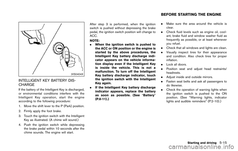
If the battery of the Intelligent Key is discharged,
or environmental conditions interfere with the
Intelligent Key operation, start the engine
according to the following procedure:
1. Move the shift lever to the P (Park) position.
2. Firmly apply the foot brake.
3. Touch the ignition switch with the IntelligentKey as illustrated. (A chime will sound.)
4. Push the ignition switch while depressing the brake pedal within 10 seconds after the
chime sounds. The engine will start. After step 3 is performed, when the ignition
switch is pushed without depressing the brake
pedal, the ignition switch position will change to
ACC.
NOTE:
.
When the ignition switch is pushed to
the ACC or ON position or the engine is
started by the above procedures, the
Intelligent Key battery discharge indi-
cator appears on the vehicle informa-
tion display even if the Intelligent Key
is inside the vehicle. This is not a
malfunction. To turn off the Intelligent
Key battery discharge indicator, touch
the ignition switch with the Intelligent
Key again.
. If the Intelligent Key battery discharge
indicator appears, replace the battery
as soon as possible. (See “Battery”
(P.8-11) .) .
Make sure the area around the vehicle is
clear.
. Check fluid levels such as engine oil, cool-
ant, brake fluid and window washer fluid as
frequently as possible, or at least whenever
you refuel.
. Check that all windows and lights are clean.
. Visually inspect tires for their appearance
and condition. Also check tires for proper
inflation.
. Lock all doors.
. Position seat and adjust head restraints/
headrests.
. Adjust inside and outside mirrors.
. Fasten seat belts and ask all passengers to
do likewise.
. Check the operation of warning lights when
the ignition switch is pushed to the ON
position. (See “Warning lights, indicator
lights and audible reminders” (P.2-10) .)
Starting and driving5-15
BEFORE STARTING THE ENGINE
Page 358 of 614
1. Make sure that the Intelligent Key is on you.
2. Depress the brake pedal.
3. Push the ignition switch once to the ONposition.
For additional information about the remote
engine start function, see “Remote engine start”
(P.3-19) .ENGINE PROTECTION MODE
The engine has an engine protection mode to
reduce the chance of damage if the coolant
temperature becomes too high (for example,
when climbing steep grades in high temperature
with heavy loads, such as when towing a trailer) .
When the engine temperature reaches a certain
level:
. The engine coolant temperature gauge will
move toward the H position.
. Engine power may be reduced.
. The air conditioning cooling function may be
automatically turned OFF for a short time
(the blower will continue to operate) .
Engine power and, under some conditions,
vehicle speed will decrease. Vehicle speed can
be controlled with the accelerator pedal, but the
vehicle may not accelerate at the desired speed.
The transmission will downshift or upshift as it
reaches prescribed shift points. You can also
shift manually.
As driving conditions change and engine cool-
ant temperature is reduced, vehicle speed can
be increased using the accelerator pedal, and
air conditioning cooling function will automati-
cally be turned back ON. If:
1. The engine coolant temperature is not
reduced.
2. The air conditioning cooling function does not turn back ON.
3. The engine oil pressure warning light
illuminates or engine coolant temperature
gauge does not return to the normal range
from the H position, this may indicate a
malfunction. Move the vehicle off the road to
a safe area and allow the engine to cool. If
after checking the oil and coolant, the
remains on or engine coolant temperature
does not return to the normal range, do not
continue to drive. It is recommended you
contact a NISSAN dealer.
The Malfunction Indicator Light (MIL)
may
also come ON. You do not need to have your
vehicle towed, unless it remains on, but have it
inspected soon. It is recommended you contact
a NISSAN dealer for this service. See “Warning
lights, indicator lights and audible reminders”
(P.2-10) .
WARNING
Overheating can result in reduced en-
gine power and vehicle speed. The
Starting and driving5-17
DRIVING THE VEHICLE
Page 373 of 614
5-32Starting and driving
LDP system:If the vehicle is parked in direct
sunlight under high temperature conditions (over
approximately 1048F (408C)) and then the LDP
system is turned on, the LDP system will be
turned off automatically, a beep will sound and
the LDP ON indicator light (green)
*1will blink.
The LDW and LDP systems are not available
until the conditions no longer exist.
Action to take:
When the above conditions no longer exist, the
LDW system will resume automatically.
For the LDP system, push the dynamic driver
assistance switch
*3again to turn the LDP
system back on.
SYSTEM MALFUNCTION
LDW system: When the LDW system malfunc-
tions, it will cancel automatically, and the LDW
indicator light (orange) will illuminate.
LDP system: When the LDP system malfunc-
tions, it will be turned off automatically, a beep
will sound, and the LDW indicator light (orange)
will illuminate.
Action to take:
Stop the vehicle in a safe location, place the
vehicle in the P (Park) position, turn the engine
off and restart the engine. If the LDW indicator
light (orange) continues to illuminate, have the
system checked. It is recommended you visit a NISSAN dealer for this service.
SSD0453
SYSTEM MAINTENANCE
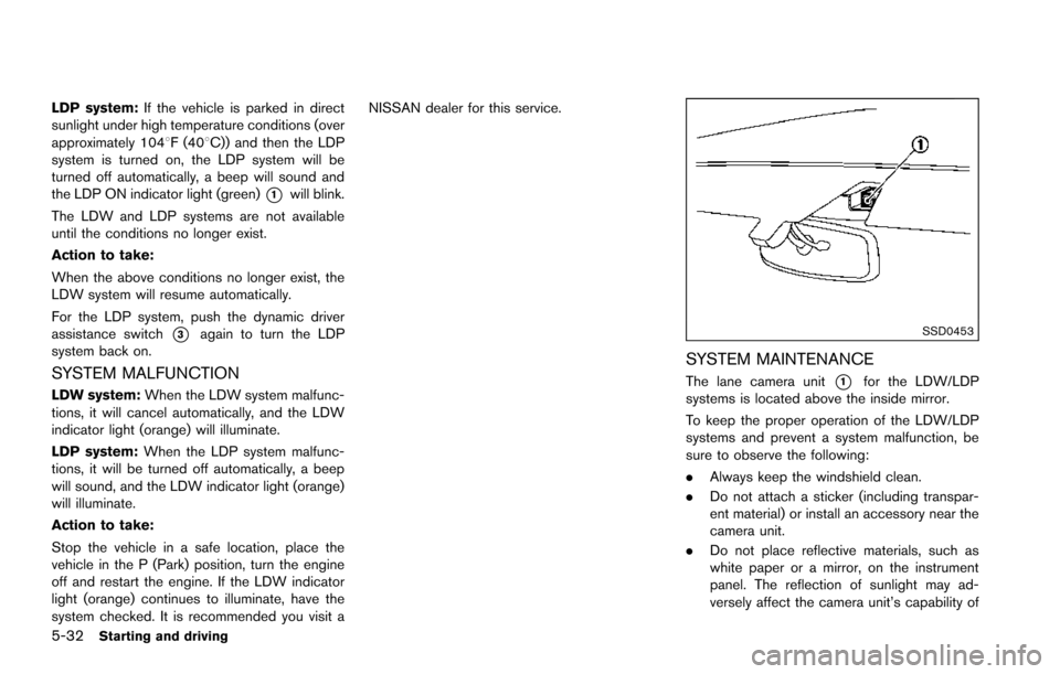
The lane camera unit*1for the LDW/LDP
systems is located above the inside mirror.
To keep the proper operation of the LDW/LDP
systems and prevent a system malfunction, be
sure to observe the following:
. Always keep the windshield clean.
. Do not attach a sticker (including transpar-
ent material) or install an accessory near the
camera unit.
. Do not place reflective materials, such as
white paper or a mirror, on the instrument
panel. The reflection of sunlight may ad-
versely affect the camera unit’s capability of
Page 383 of 614
5-42Starting and driving
Action to take:
Stop the vehicle in a safe location, place the
vehicle in the P (Park) position, turn the engine
off and restart the engine.
If the BSW system warning light continues to
illuminate, have the system checked. It is
recommended you visit a NISSAN dealer for
this service.
JVS0908X
SYSTEM MAINTENANCE
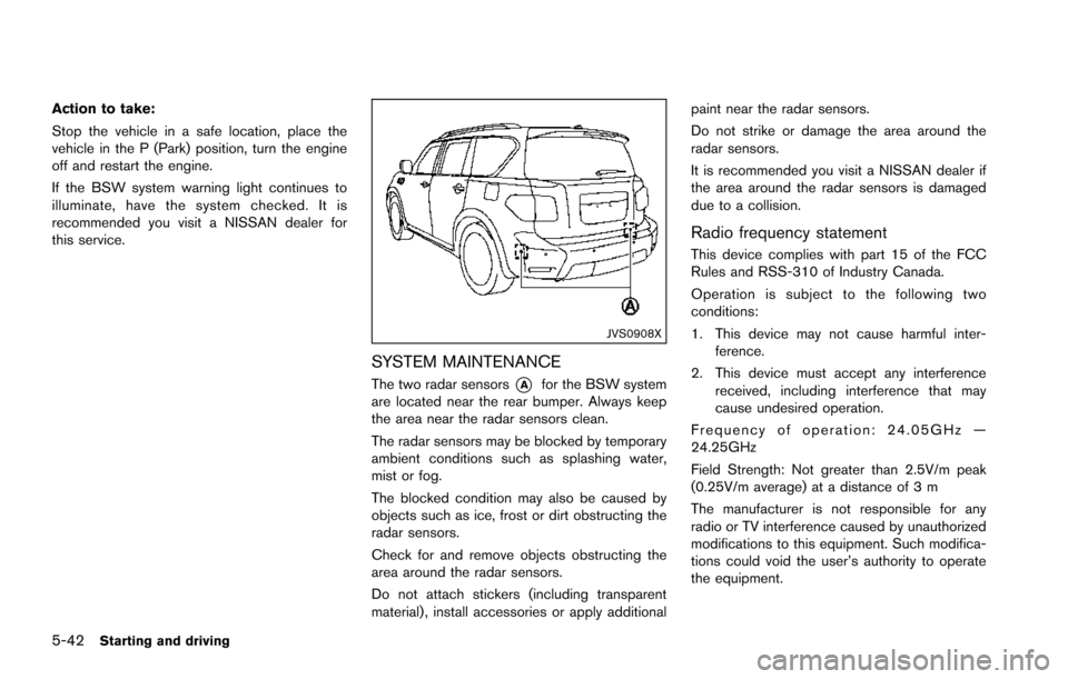
The two radar sensors*Afor the BSW system
are located near the rear bumper. Always keep
the area near the radar sensors clean.
The radar sensors may be blocked by temporary
ambient conditions such as splashing water,
mist or fog.
The blocked condition may also be caused by
objects such as ice, frost or dirt obstructing the
radar sensors.
Check for and remove objects obstructing the
area around the radar sensors.
Do not attach stickers (including transparent
material) , install accessories or apply additional paint near the radar sensors.
Do not strike or damage the area around the
radar sensors.
It is recommended you visit a NISSAN dealer if
the area around the radar sensors is damaged
due to a collision.
Radio frequency statement
This device complies with part 15 of the FCC
Rules and RSS-310 of Industry Canada.
Operation is subject to the following two
conditions:
1. This device may not cause harmful inter-
ference.
2. This device must accept any interference received, including interference that may
cause undesired operation.
Frequency of operation: 24.05GHz —
24.25GHz
Field Strength: Not greater than 2.5V/m peak
(0.25V/m average) at a distance of 3 m
The manufacturer is not responsible for any
radio or TV interference caused by unauthorized
modifications to this equipment. Such modifica-
tions could void the user’s authority to operate
the equipment.
Page 396 of 614
Action to take:
When the above conditions no longer exist, turn
the BSI system off and turn it on again. If the BSI
system warning light (orange)
*1continues to
blink even after the BSI system is turned on
again, stop the vehicle in a safe location, place
the shift lever in the P (Park) position and turn
the engine off. Check for and remove objects
obscuring the radar sensors on the rear bumper,
and restart the engine.
If the BSI system warning light (orange)
*1continues to blink, have the BSI system
checked. It is recommended you visit a NISSAN
dealer for this service.
SYSTEM MALFUNCTION
When the BSI system malfunctions, it will be
turned off automatically, a chime will sound and
the BSI system warning light (orange) will
illuminate.
Action to take:
Stop the vehicle in a safe location, place the shift
lever in the P (Park) position, turn the engine off
and restart the engine.
If the warning light (orange) continues to
illuminate, have the BSI system checked. It is
recommended you visit a NISSAN dealer for this
service.
JVS0910X
SYSTEM MAINTENANCE
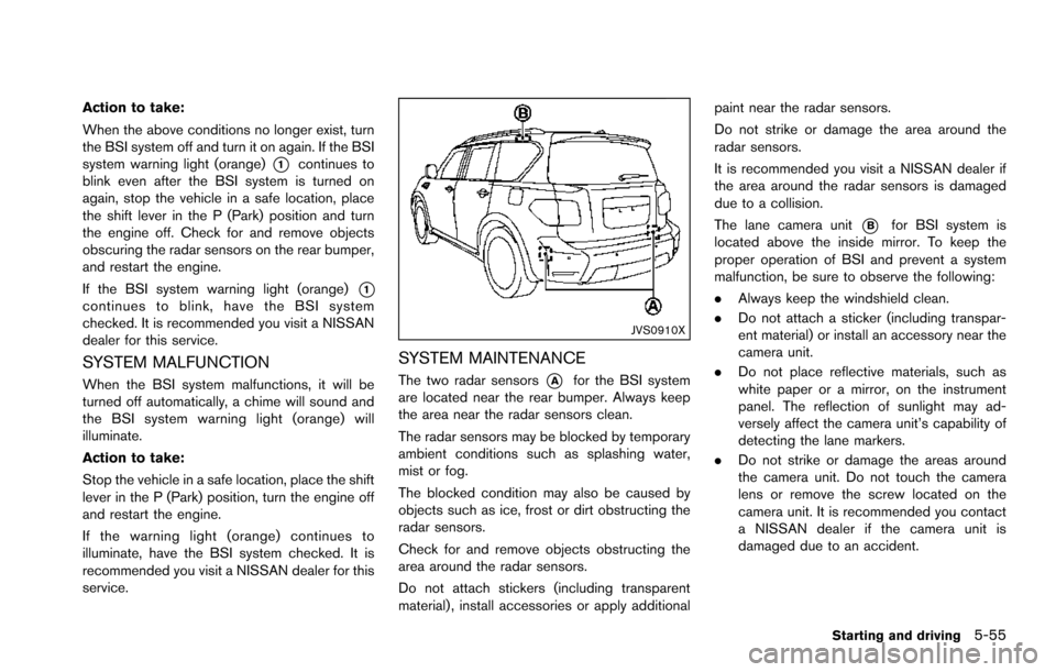
The two radar sensors*Afor the BSI system
are located near the rear bumper. Always keep
the area near the radar sensors clean.
The radar sensors may be blocked by temporary
ambient conditions such as splashing water,
mist or fog.
The blocked condition may also be caused by
objects such as ice, frost or dirt obstructing the
radar sensors.
Check for and remove objects obstructing the
area around the radar sensors.
Do not attach stickers (including transparent
material) , install accessories or apply additional paint near the radar sensors.
Do not strike or damage the area around the
radar sensors.
It is recommended you visit a NISSAN dealer if
the area around the radar sensors is damaged
due to a collision.
The lane camera unit
*Bfor BSI system is
located above the inside mirror. To keep the
proper operation of BSI and prevent a system
malfunction, be sure to observe the following:
. Always keep the windshield clean.
. Do not attach a sticker (including transpar-
ent material) or install an accessory near the
camera unit.
. Do not place reflective materials, such as
white paper or a mirror, on the instrument
panel. The reflection of sunlight may ad-
versely affect the camera unit’s capability of
detecting the lane markers.
. Do not strike or damage the areas around
the camera unit. Do not touch the camera
lens or remove the screw located on the
camera unit. It is recommended you contact
a NISSAN dealer if the camera unit is
damaged due to an accident.
Starting and driving5-55