2017 NISSAN ARMADA fog light
[x] Cancel search: fog lightPage 131 of 614
2-42Instruments and controls
SIC3672
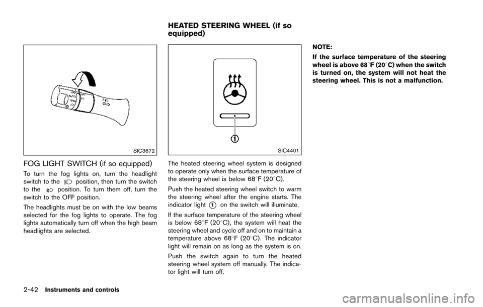
FOG LIGHT SWITCH (if so equipped)
To turn the fog lights on, turn the headlight
switch to theposition, then turn the switch
to theposition. To turn them off, turn the
switch to the OFF position.
The headlights must be on with the low beams
selected for the fog lights to operate. The fog
lights automatically turn off when the high beam
headlights are selected.
SIC4401
The heated steering wheel system is designed
to operate only when the surface temperature of
the steering wheel is below 688F (208C) .
Push the heated steering wheel switch to warm
the steering wheel after the engine starts. The
indicator light
*1on the switch will illuminate.
If the surface temperature of the steering wheel
is below 688F (208C) , the system will heat the
steering wheel and cycle off and on to maintain a
temperature above 688F (208C) . The indicator
light will remain on as long as the system is on.
Push the switch again to turn the heated
steering wheel system off manually. The indica-
tor light will turn off. NOTE:
If the surface temperature of the steering
wheel is above 688F (208C) when the switch
is turned on, the system will not heat the
steering wheel. This is not a malfunction.
HEATED STEERING WHEEL (if so
equipped)
Page 252 of 614
A visible mist may be seen coming from the
ventilators in hot, humid conditions as the air is
cooled rapidly. This does not indicate a mal-
function.
Dehumidified defrosting or defogging:
1. Push the “
” front defroster button. (The
indicator light on the button will illuminate.)
2. Turn the temperature control dial to set the desired temperature.
. To quickly remove ice from the outside of the
windows, push the fan speed increase
button “
” and set it to the maximum
position.
. As soon as possible after the windshield is
clean, push the “AUTO” button to return to
the auto mode.
. When the “
” front defroster button is
pushed, the air conditioner will automatically
be turned on at outside temperatures above
238F( �í58C) to defog the windshield, and
the air recirculate mode will automatically be
turned off.
Outside air is drawn into the passenger
compartment to improve the defogging
performance.
Manual operation
Fan speed control:
Push the fan speed increase “
” or decrease
“” buttons to manually control the fan speed.
Push the “AUTO” button to return to automatic
control of the fan speed.
Temperature control:
Turn the temperature control dial to set the
desired temperature.
Air flow control:
Pushing the “MODE” manual air flow control
button selects the air outlet to:
: Air flows from center and side ventilators.
: Air flows from center and side ventilators and foot outlets.
: Air flows mainly from foot outlets.
: Air flows from defroster and foot outlets.
Air intake control:
. Push the “
” air recirculation button to
recirculate interior air inside the vehicle. The
“
” indicator light on the button will come
on. The air recirculation mode cannot be
activated when the air conditioner is in the
front defrosting mode “
”.
. Push the “
” outside air circulation button
to draw outside air into the passenger
compartment. The “
” indicator light on the button will come on.
. To control the air intake automatically, push
and hold either the “
” air recirculation
button or the “” outside air circulation
button (whichever indicator light is illumi-
nated) . The indicator lights (both air recir-
culation and outside air circulation buttons)
will flash twice, and then the air intake will
switch to automatic control.
Turning the system off
Push the OFF button.
Upper vent system
When the upper vent “” button is pushed,
the air flow against the driver’s or passenger’s
upper body becomes gentle. The indicator light
on the button will illuminate.
In this mode, air from the upper ventilator flows
in order to control the cabin temperature without
blowing air directly on the occupants.
Push the upper vent “
” button when you
want the air conditioner to work quickly.
To turn the system off, push the upper vent
“
” button to turn the indicator light off.
Monitor, heater, air conditioner, audio, phone and voice recognition systems4-55
Page 370 of 614
SSD1002
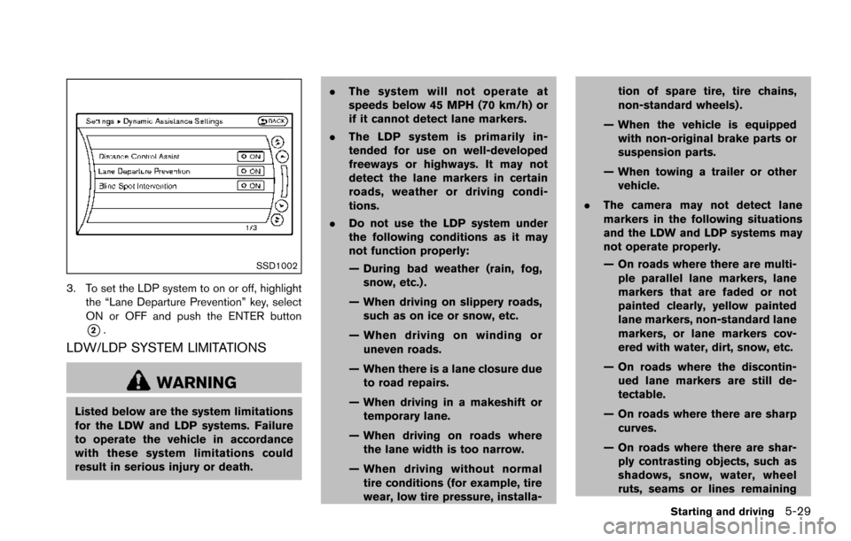
3. To set the LDP system to on or off, highlightthe “Lane Departure Prevention” key, select
ON or OFF and push the ENTER button
*2.
LDW/LDP SYSTEM LIMITATIONS
WARNING
Listed below are the system limitations
for the LDW and LDP systems. Failure
to operate the vehicle in accordance
with these system limitations could
result in serious injury or death. .
The system will not operate at
speeds below 45 MPH (70 km/h) or
if it cannot detect lane markers.
. The LDP system is primarily in-
tended for use on well-developed
freeways or highways. It may not
detect the lane markers in certain
roads, weather or driving condi-
tions.
. Do not use the LDP system under
the following conditions as it may
not function properly:
— During bad weather (rain, fog,
snow, etc.) .
— When driving on slippery roads, such as on ice or snow, etc.
— When driving on winding or uneven roads.
— When there is a lane closure due to road repairs.
— When driving in a makeshift or temporary lane.
— When driving on roads where the lane width is too narrow.
— When driving without normal tire conditions (for example, tire
wear, low tire pressure, installa- tion of spare tire, tire chains,
non-standard wheels) .
— When the vehicle is equipped with non-original brake parts or
suspension parts.
— When towing a trailer or other vehicle.
. The camera may not detect lane
markers in the following situations
and the LDW and LDP systems may
not operate properly.
— On roads where there are multi-
ple parallel lane markers, lane
markers that are faded or not
painted clearly, yellow painted
lane markers, non-standard lane
markers, or lane markers cov-
ered with water, dirt, snow, etc.
— On roads where the discontin- ued lane markers are still de-
tectable.
— On roads where there are sharp curves.
— On roads where there are shar- ply contrasting objects, such as
shadows, snow, water, wheel
ruts, seams or lines remaining
Starting and driving5-29
Page 382 of 614
JVS0687X
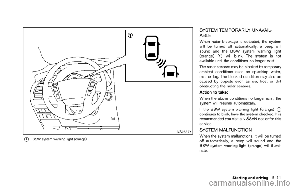
*1BSW system warning light (orange)
SYSTEM TEMPORARILY UNAVAIL-
ABLE
When radar blockage is detected, the system
will be turned off automatically, a beep will
sound and the BSW system warning light
(orange)
*1will blink. The system is not
available until the conditions no longer exist.
The radar sensors may be blocked by temporary
ambient conditions such as splashing water,
mist or fog. The blocked condition may also be
caused by objects such as ice, frost or dirt
obstructing the radar sensors.
Action to take:
When the above conditions no longer exist, the
system will resume automatically.
If the BSW system warning light (orange)
*1continues to blink, have the system checked. It is
recommended you visit a NISSAN dealer for this
service.
SYSTEM MALFUNCTION
When the system malfunctions, it will be turned
off automatically, a beep will sound and the
BSW system warning light (orange) will illumi-
nate.
Starting and driving5-41
Page 383 of 614
5-42Starting and driving
Action to take:
Stop the vehicle in a safe location, place the
vehicle in the P (Park) position, turn the engine
off and restart the engine.
If the BSW system warning light continues to
illuminate, have the system checked. It is
recommended you visit a NISSAN dealer for
this service.
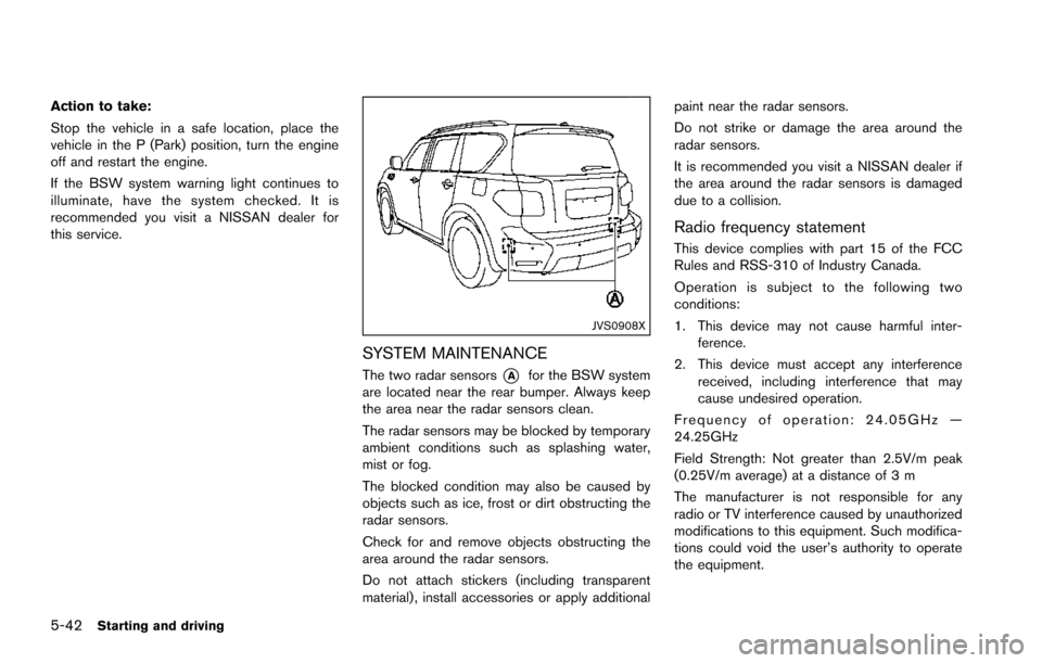
JVS0908X
SYSTEM MAINTENANCE
The two radar sensors*Afor the BSW system
are located near the rear bumper. Always keep
the area near the radar sensors clean.
The radar sensors may be blocked by temporary
ambient conditions such as splashing water,
mist or fog.
The blocked condition may also be caused by
objects such as ice, frost or dirt obstructing the
radar sensors.
Check for and remove objects obstructing the
area around the radar sensors.
Do not attach stickers (including transparent
material) , install accessories or apply additional paint near the radar sensors.
Do not strike or damage the area around the
radar sensors.
It is recommended you visit a NISSAN dealer if
the area around the radar sensors is damaged
due to a collision.
Radio frequency statement
This device complies with part 15 of the FCC
Rules and RSS-310 of Industry Canada.
Operation is subject to the following two
conditions:
1. This device may not cause harmful inter-
ference.
2. This device must accept any interference received, including interference that may
cause undesired operation.
Frequency of operation: 24.05GHz —
24.25GHz
Field Strength: Not greater than 2.5V/m peak
(0.25V/m average) at a distance of 3 m
The manufacturer is not responsible for any
radio or TV interference caused by unauthorized
modifications to this equipment. Such modifica-
tions could void the user’s authority to operate
the equipment.
Page 390 of 614
.Do not use the BSI system under the
following conditions because the
system may not function properly.
— During bad weather. (For exam-
ple: rain, fog, snow, etc.)
— When driving on slippery roads, such as on ice or snow, etc.
— When driving on winding or uneven roads.
— When there is a lane closure due to road repairs.
— When driving in a makeshift or temporary lane.
— When driving on roads where the lane width is too narrow.
— When driving with a tire that is not within normal tire conditions
(for example, tire wear, low tire
pressure, installation of spare
tire, tire chains, non-standard
wheels) .
— When the vehicle is equipped with non-original brake parts or
suspension parts.
— When towing a trailer or other vehicle. .
Excessive noise (for example, audio
system volume, open vehicle win-
dow) will interfere with the chime
sound, and it may not be heard.
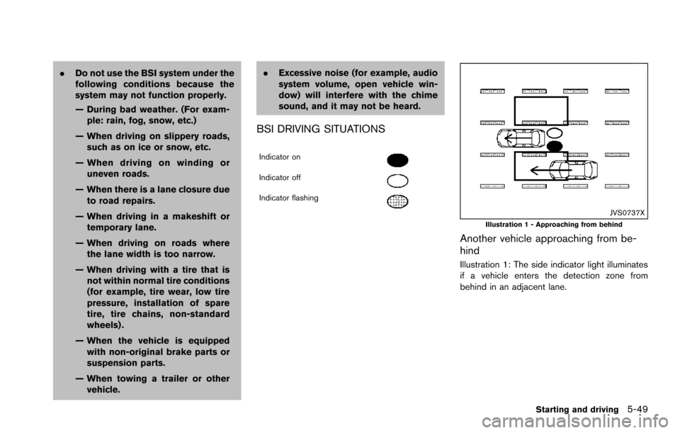
BSI DRIVING SITUATIONS
Indicator on
Indicator off
Indicator flashing
JVS0737XIllustration 1 - Approaching from behind
Another vehicle approaching from be-
hind
Illustration 1: The side indicator light illuminates
if a vehicle enters the detection zone from
behind in an adjacent lane.
Starting and driving5-49
Page 395 of 614
5-54Starting and driving
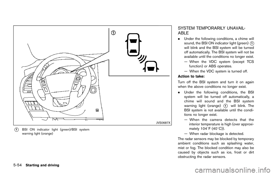
JVS0687X
*1BSI ON indicator light (green)/BSI system
warning light (orange)
SYSTEM TEMPORARILY UNAVAIL-
ABLE
.Under the following conditions, a chime will
sound, the BSI ON indicator light (green)
*1will blink and the BSI system will be turned
off automatically. The BSI system will not be
available until the conditions no longer exist.
— When the VDC system (except TCS
function) or ABS operates.
— When the VDC system is turned off.
Action to take:
Turn off the BSI system and turn it on again
when the above conditions no longer exist.
. Under the following conditions, the BSI
system will be turned off automatically, a
chime will sound and the BSI system
warning light (orange)
*1will blink. The
BSI system is not available until the condi-
tions no longer exist.
— When the camera detects that the
interior temperature is high (over approxi-
mately 1048F (408C)) .
— When radar blockage is detected.
The radar sensors may be blocked by temporary
ambient conditions such as splashing water,
mist or fog. The blocked condition may also be
caused by objects such as ice, frost or dirt
obstructing the radar sensors.
Page 396 of 614
Action to take:
When the above conditions no longer exist, turn
the BSI system off and turn it on again. If the BSI
system warning light (orange)
*1continues to
blink even after the BSI system is turned on
again, stop the vehicle in a safe location, place
the shift lever in the P (Park) position and turn
the engine off. Check for and remove objects
obscuring the radar sensors on the rear bumper,
and restart the engine.
If the BSI system warning light (orange)
*1continues to blink, have the BSI system
checked. It is recommended you visit a NISSAN
dealer for this service.
SYSTEM MALFUNCTION
When the BSI system malfunctions, it will be
turned off automatically, a chime will sound and
the BSI system warning light (orange) will
illuminate.
Action to take:
Stop the vehicle in a safe location, place the shift
lever in the P (Park) position, turn the engine off
and restart the engine.
If the warning light (orange) continues to
illuminate, have the BSI system checked. It is
recommended you visit a NISSAN dealer for this
service.
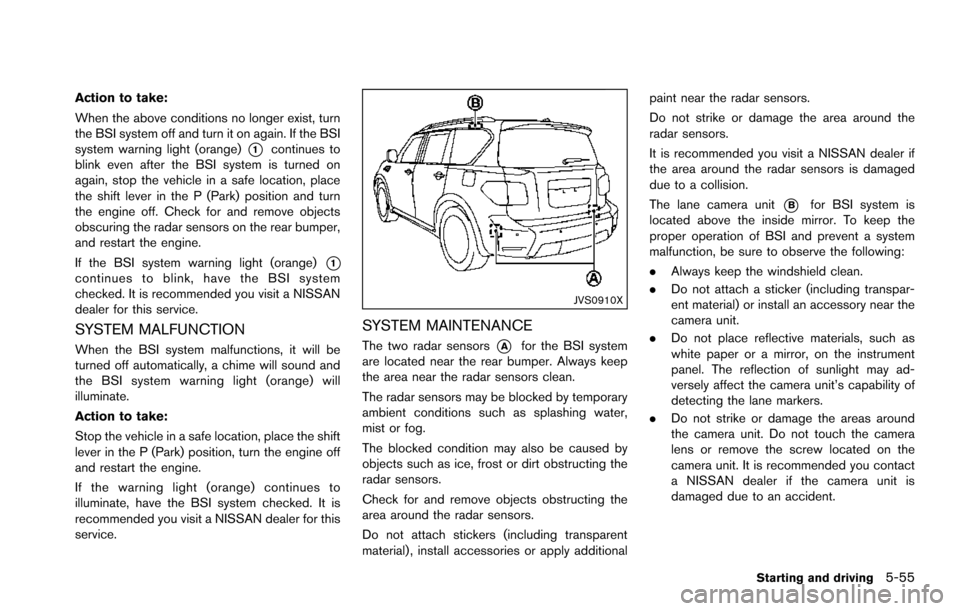
JVS0910X
SYSTEM MAINTENANCE
The two radar sensors*Afor the BSI system
are located near the rear bumper. Always keep
the area near the radar sensors clean.
The radar sensors may be blocked by temporary
ambient conditions such as splashing water,
mist or fog.
The blocked condition may also be caused by
objects such as ice, frost or dirt obstructing the
radar sensors.
Check for and remove objects obstructing the
area around the radar sensors.
Do not attach stickers (including transparent
material) , install accessories or apply additional paint near the radar sensors.
Do not strike or damage the area around the
radar sensors.
It is recommended you visit a NISSAN dealer if
the area around the radar sensors is damaged
due to a collision.
The lane camera unit
*Bfor BSI system is
located above the inside mirror. To keep the
proper operation of BSI and prevent a system
malfunction, be sure to observe the following:
. Always keep the windshield clean.
. Do not attach a sticker (including transpar-
ent material) or install an accessory near the
camera unit.
. Do not place reflective materials, such as
white paper or a mirror, on the instrument
panel. The reflection of sunlight may ad-
versely affect the camera unit’s capability of
detecting the lane markers.
. Do not strike or damage the areas around
the camera unit. Do not touch the camera
lens or remove the screw located on the
camera unit. It is recommended you contact
a NISSAN dealer if the camera unit is
damaged due to an accident.
Starting and driving5-55