Page 13 of 497
1. Instrument brightness control (P. 2-34)Trip computer reset switch (P. 2-3)
2. Vents (P. 4-16)
3. Headlight/fog light (if so equipped)/turn
signal switch (P. 2-34)
4. Driver supplemental air bag (P. 1-42) Horn (P. 2-39)
5. Meters and gauges (P. 2-3) Warning and indicator lights (P. 2-10)
Vehicle information display (P. 2-17)
6. Paddle shift controls (if so equipped)
(P. 5-13)
7. Wiper and washer switch (P. 2-32)
8. Hazard warning flasher switch (P. 6-2)
9. Front passenger air bag status light
(P. 1-42)
10. Navigation system* (if so equipped)
(P. 4-4)
11. Front passenger supplemental air bag
(P. 1-42)
12. Glove box (P. 2-44)
13. Power outlet (P. 2-42)
14. Heater and air conditioner (P. 4-17)
15. Shift lever (P. 5-13)
16. USB connection port (if so equipped)
(P. 4-27)
Aux jack (P. 4-27)
LII2360
INSTRUMENT PANEL
0-6Illustrated table of contents
Page 14 of 497
17. Push-button ignition switch (P. 5-8)
18. Cruise control main/set switches(if so equipped) (P. 5-41)
Intelligent Cruise Control (ICC)
switches (if so equipped) (P. 5-41)
Bluetooth® Hands-free Phone System
(P. 4-27)
19. Tilt/telescopic steering wheel controls
(P. 3-35)
20. Vehicle information display controls
(P. 2-17)
Steering wheel switch for audio control
(P. 4-27)
21. Hood release (P. 3-30)
22. Trunk opener (P. 3-30) Vehicle Dynamic Control (VDC) OFF
switch (P. 2-41)
Heated steering wheel switch
(if so equipped) (P. 2-40)
*: Refer to the separate Navigation System Own-
er’s Manual (if so equipped) .
Refer to the page number indicated in pa-
rentheses for operating details.
Illustrated table of contents0-7
Page 76 of 497
 activate, smoke is re-
leased and a loud noise may be heard. This
smoke is not harmful and does not indicate a fire.
Care should be taken not to inhale it, as it may
cause irritat")
When pretensioner(s) activate, smoke is re-
leased and a loud noise may be heard. This
smoke is not harmful and does not indicate a fire.
Care should be taken not to inhale it, as it may
cause irritation and choking. Those with a history
of a breathing condition should get fresh air
promptly.
After the pretensioner(s’) activation, load limiters
allow the seat belt to release webbing (if neces-
sary) to reduce forces against the chest.
The supplemental air bag warning light
is
used to indicate malfunctions in the pretensioner
system. For additional information, refer to
�Supplemental air bag warning light� in this sec-
tion. If the operation of the supplemental air bag
warning light indicates there is a malfunction,
have the system checked. It is recommended that
you visit a NISSAN dealer for this service.
When selling your vehicle, we request that you
inform the buyer about the pretensioner system
and guide the buyer to the appropriate sections
in this Owner’s Manual.
1. SRS air bag warning labels (located on
the sun visors)
SUPPLEMENTAL AIR BAG
WARNING LABELS
Warning labels about the supplemental front-
impact air bag system are placed in the vehicle as
shown in the illustration.
WARNING
Do not use a rear-facing child restraint on
a seat protected by an air bag in front of it.
If the air bag deploys, it may cause serious
injury or death.
SUPPLEMENTAL AIR BAG
WARNING LIGHT
The supplemental air bag warning light,
displaying
in the instrument panel, moni-
tors the circuits for the air bag systems, preten-
sioner(s) and all related wiring.
When the ignition is placed in the ON or START
position, the supplemental air bag warning light
illuminates for about 7 seconds and then turns
off. This means the system is operational.
LRS2163LRS0100
Safety—Seats, seat belts and supplemental restraint system1-59
Page 79 of 497

2 Instruments and controls
Instrument panel...................................2-2
Meters and gauges ................................2-3
Speedometer and odometer .....................2-4
Tachometer ....................................2-5
Engine coolant temperature gauge ...............2-5
Fuel gauge ....................................2-6
Compass (if so equipped) ..........................2-7
Compass display ...............................2-7
Warning lights, indicator lights and audible
reminders ........................................ 2-10
Checking lights ............................... 2-10
Warning lights ................................ 2-11
Indicator lights ................................ 2-15
Audible reminders ............................. 2-17
Vehicle information display ......................... 2-17
How to use the vehicle information display .......2-18
Startup display ................................ 2-18
Resetting the trip computer .....................2-19
Settings ...................................... 2-19
Vehicle information display warnings and
indicators ..................................... 2-25
Security systems ................................. 2-29
Vehicle security system ......................... 2-29NISSAN Vehicle Immobilizer System
.............2-31
Wiper and washer switch ......................... 2-32
Switch operation .............................. 2-32
Rear window and outside mirror (if so equipped)
defroster switch .................................. 2-33
Headlight and turn signal switch ....................2-34
Headlight control switch ........................ 2-34
Daytime Running Light (DRL) system
(Type A) (if so equipped) .......................2-36
LED Daytime Running Light (DRL) system
(Type B) (if so equipped) .......................2-37
Instrument brightness control ...................2-37
Turn signal switch ............................. 2-38
Fog light switch (if so equipped) ................2-38
Horn ............................................ 2-39
Heated seat switches (if so equipped) ..............2-39
Heated steering wheel switch (if so equipped) .......2-40
V
ehicle Dynamic Control (VDC) off switch ...........2-41
E-call (SOS) switch (if so equipped) ................2-41
Power outlets .................................... 2-42
Extended storage switch .......................... 2-43
Storage ......................................... 2-44
Front-door pockets ............................ 2-44
Seatback pockets (if so equipped) ..............2-44
Page 81 of 497
1. Instrument brightness control (P. 2-34)Trip computer reset switch (P. 2-3)
2. Vents (P. 4-16)
3. Headlight/fog light (if so equipped)/turn
signal switch (P. 2-34)
4. Driver supplemental air bag (P. 1-42) Horn (P. 2-39)
5. Meters and gauges (P. 2-3) Warning and indicator lights (P. 2-10)
Vehicle information display (P. 2-17)
6. Paddle shift controls (if so equipped)
(P. 5-13)
7. Wiper and washer switch (P. 2-32)
8. Hazard warning flasher switch (P. 6-2)
9. Front passenger air bag status light
(P. 1-42)
10. Navigation system* (if so equipped)
(P. 4-4)
11. Front passenger supplemental air bag
(P. 1-42)
12. Glove box (P. 2-44)
13. Power outlet (P. 2-42)
14. Heater and air conditioner (P. 4-17)
15. Shift lever (P. 5-13)
16. USB connection port (if so equipped)
(P. 4-27)
Aux jack (P. 4-27)
LII2360
INSTRUMENT PANEL
2-2Instruments and controls
Page 82 of 497
17. Push-button ignition switch (P. 5-8)
18. Cruise control main/set switches(if so equipped) (P. 5-41)
Intelligent Cruise Control (ICC)
switches (if so equipped) (P. 5-41)
Bluetooth® Hands-free Phone System
(P. 4-27)
19. Tilt/telescopic steering wheel controls
(P. 3-35)
20. Vehicle information display controls
(P. 2-17)
Steering wheel switch for audio control
(P. 4-27)
21. Hood release (P. 3-30)
22. Trunk opener (P. 3-30) Vehicle Dynamic Control (VDC) OFF
switch (P. 2-41)
Heated steering wheel switch
(if so equipped) (P. 2-40)
*: Refer to the separate Navigation System Own-
er’s Manual (if so equipped) .
Refer to the page number indicated in pa-
rentheses for operating details.
1. Tachometer
2. Warning and indicator lights
3. Vehicle information displayOdometer
Twin trip odometer 4. Speedometer
5. Fuel gauge
6. Engine coolant temperature gauge
LIC3459
METERS AND GAUGES
Instruments and controls2-3
Page 83 of 497
SPEEDOMETER AND ODOMETER
This vehicle is equipped with a speedometer and
odometer. The speedometer is located on the
right side of the meter cluster. The odometer is
located within the vehicle information display.
Speedometer
The speedometer indicates vehicle speed.
Odometer/Twin trip odometer
The odometer and the twin trip odometer�1are
displayed in the vehicle information display when
the ignition switch is placed in the ON position.
The odometer records the total distance the ve-
hicle has been driven.
The twin trip odometer records the distance of
individual trips.
LIC2218LIC2921
2-4Instruments and controls
Page 84 of 497
Changing the display
Push the TRIP RESET
�2switch on the left side
of the instrument panel to change the display as
follows:
Trip
→ Trip→Odometer Mileage →
Trip
Resetting the trip odometer
Pushing the TRIP RESET switch
�2for more
than 1 second resets the currently displayed trip
odometer to zero.
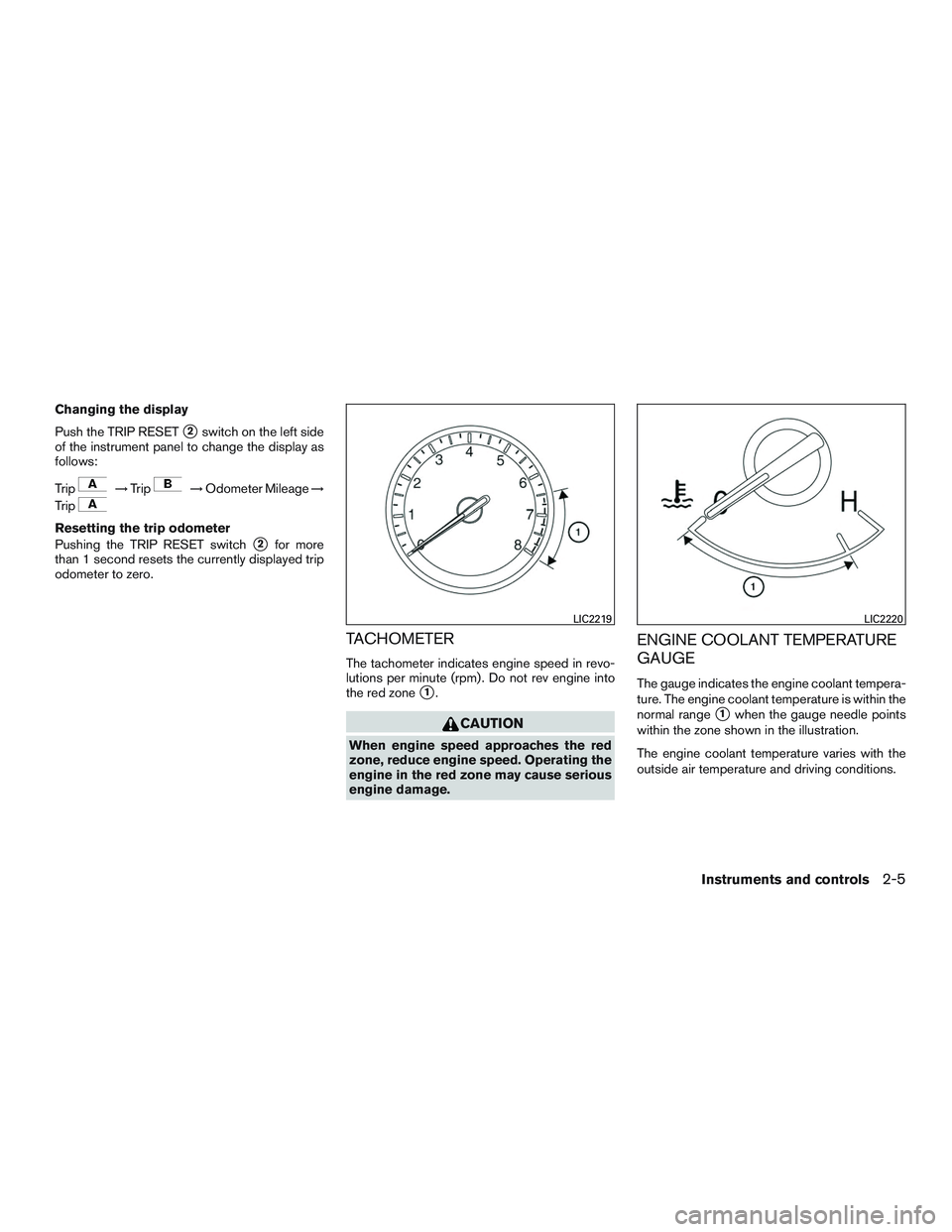
TACHOMETER
The tachometer indicates engine speed in revo-
lutions per minute (rpm) . Do not rev engine into
the red zone
�1.
CAUTION
When engine speed approaches the red
zone, reduce engine speed. Operating the
engine in the red zone may cause serious
engine damage.
ENGINE COOLANT TEMPERATURE
GAUGE
The gauge indicates the engine coolant tempera-
ture. The engine coolant temperature is within the
normal range
�1when the gauge needle points
within the zone shown in the illustration.
The engine coolant temperature varies with the
outside air temperature and driving conditions.
LIC2219LIC2220
Instruments and controls2-5
Trip computer reset switch (P. 2-3)
2. Vents (P. 4-16)
3. Headlight/fog light (if so equipped)/turn
signal switch (P. 2-34)
4. Driver supplemental air bag (P.")

18. Cruise control main/set switches(if so equipped) (P. 5-41)
Intelligent Cruise Control (ICC)
switches (if so equipped) (P. 5-41)
Bluetooth® Hands-free Phon")